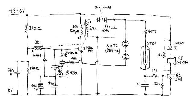
Making a Geiger counter is really very simple. All it needs is an inverter to provide a regulated supply of 450V or so (depending on the particular Geiger tube, but 450V seems to be OK for most readily available tubes) and something to go click.
The Geiger tube used here is a Russian type STS5 (or CTC5 in Cyrillic). These detect gammas and betas, and are widely available from various internet sellers. The biggest problem is finding a seller who can be paid by some other means than Paypal, because Paypal are a bunch of fucking wankers who I can't use because they don't like people called Pigeon. So Paypal can go and fuck themselves, the bunch of prejudiced cunts. I ended up buying mine from Arthur Bernard on Etsy, who gave very good and fast service, and accepts normal cards without forcing you to use fucking Paypal.
Connections to this tube are made by 7mm diameter studs on the ends, which fit neatly into a pair of fuse holder clips.
The transformer is the other awkward component. The one I used was scrounged out of an old PC PSU. This is not very helpful when it comes to sourcing another one. However it looks as if Epcos B65807J0000R097 (Farnell stock number 2355150) or Epcos B65541D0000R048 (Farnell stock number 2355052) would be suitable cores to wind one on, with the numbers of turns given on the circuit diagram. Or indeed with more turns on the secondary if you want to make it work off a lower supply voltage. The output impedance of this inverter is around 330k which is buckets for such a mild duty as this.
The KSE13001 transistor was scrounged out of a dud CFL. Something like a ZTX857 would probably be better but I didn't have one and I did have a dud CFL so KSE13001 it was.
The HT is regulated using a series string of five T2 wire ended neons. The linked Farnell listing quotes "Supply voltage 240V" which is wrong and if you connect them across 240V they will explode. In fact they have a striking voltage of 90V. When they strike they supply base current to a Darlington pair of BC548s which shunts the base drive of the KSE13001 to a negative rail provided by catching the negative excursions of the base drive. An LED in the collector of the first BC548 illuminates when this is happening to provide a "POWER OK" indication. One might think that the neons could be used for this but the current through them is so small that you can barely see them light up.
Some people like to use high voltage Zeners for this sort of job, but I don't. Quite apart from the fact that I don't have any but I do have lots of neons, Zeners have a comparatively soft knee and let significant current pass below their quoted breakdown voltage, which means that in a circuit such as this where the regulation department is sensitive to only a few microamps you never quite know what's going on. Neons let zero current through below their breakdown voltage so the design process is much more definite, especially at very low currents where there is very little difference between striking and running voltage. Zeners are also fucking unreliable. If a semiconductor component in a commercial power supply fails of its own accord (as opposed to failing as a result of something else going wrong, which is what usually takes out the power devices) it is more likely to be a Zener than anything else. So I prefer not to use them unless there is no alternative.
The Russians made a neon regulator tube (SG301S-1 / СГ301С-1) specifically for regulating the output of inverters to drive this Geiger tube. (I forget the type number.) It would have been cool to use one of these but Arthur Bernard didn't have one and the only people who did have one only accept payment through fucking pay cunt pal shitewank.
The output pulses from the Geiger tube switch another BC548 which drives a piezo beeper. This produces very short beeps which sound like clicks but are much easier to hear. According to the RS website the part 249-794 has been discontinued but they suggest 511-7642 as an alternative and it looks to be the same thing. There is also an LED in series which flashes for every pulse because all good circuits ought to have a flashing LED.
It would be possible to put the input side of an optoisolator in series with the LED and beeper to provide an isolated output to feed to a computer or whatever. Alternatively a counting circuit can be made using CMOS logic chips (eg. 4026) running off the same power supply, and the clock signal taken directly from the collector, which is what I did to make the plot below. The 1k2 resistor in parallel with the LED and beeper is to prevent the unsteady current drawn by the beeper from causing multiple counts in such a setup.
Both the LEDs in this circuit should be high intensity types which provide a good bright output from a low current. This is particularly important for the POWER OK indicator which only gets about 0.5mA or less.
Self-oscillating switched mode power supplies usually include an arse-kicking resistor from the AC side of the input rectifier to some point in the oscillator circuit to make sure it starts properly. Things which include such a circuit often stop working after a while because the manufacturers are cunts and have used an ordinary film resistor for this job. Ordinary film resistors do not like having high voltages applied even if the dissipation is much less than the rating, and go open circuit after a bit. Because of this the 4M7 and 10M resistors should either be types suitable for high voltage applications (such as the old bulk-composition ones used in the days of valves), or should be made with ten 470k/1M resistors in series or something like that. Mind you in this particular application it probably doesn't make much difference.
To test this device I used a 33kBq 241Am source out of an old smoke detector. This is nominally an alpha source but it also provides 60keV gammas from relaxation of the 237Np nucleus formed in an excited state from the alpha decay of the 241Am. These gammas produce around 330cpm with the source 1cm or so from the Geiger tube. Background is about 25cpm, which agrees with what the tube data says it should be.

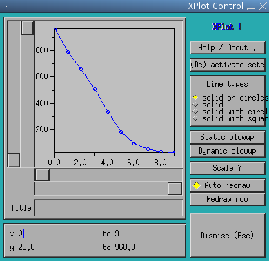
Here is a plot of counts per minute against log2 of distance between the source and the tube. As you can see it is a pretty good straight line until the count gets down to the level where the background count starts messing it up. I took 8 readings for each distance, counting for 1 minute each time, and the same without the source present to get the background count. The raw data is below. Distances are in mm.
| Distance | Count | Count | Count | Count | Count | Count | Count | Count | Average |
| 0 | 964 | 1010 | 954 | 929 | 1008 | 1002 | 987 | 897 | 968.875 |
| 1 | 782 | 825 | 764 | 793 | 802 | 771 | 798 | 803 | 792.25 |
| 2 | 668 | 672 | 669 | 617 | 658 | 624 | 662 | 723 | 661.625 |
| 4 | 526 | 503 | 501 | 529 | 521 | 470 | 492 | 506 | 506.0 |
| 8 | 341 | 326 | 336 | 336 | 372 | 340 | 330 | 310 | 336.375 |
| 16 | 192 | 187 | 166 | 183 | 194 | 170 | 199 | 174 | 183.125 |
| 32 | 99 | 90 | 81 | 97 | 77 | 87 | 121 | 95 | 93.375 |
| 64 | 53 | 64 | 66 | 48 | 46 | 56 | 51 | 43 | 53.375 |
| 128 | 42 | 40 | 28 | 27 | 32 | 36 | 32 | 37 | 34.25 |
| 256 | 32 | 28 | 26 | 28 | 25 | 33 | 18 | 24 | 26.75 |
| BG | 27 | 22 | 25 | 18 | 29 | 21 | 22 | 30 | 24.25 |
So now you can determine whether you have been nuked even if you are asleep when they do it.
Back to Pigeon's Nest
Be kind to pigeons