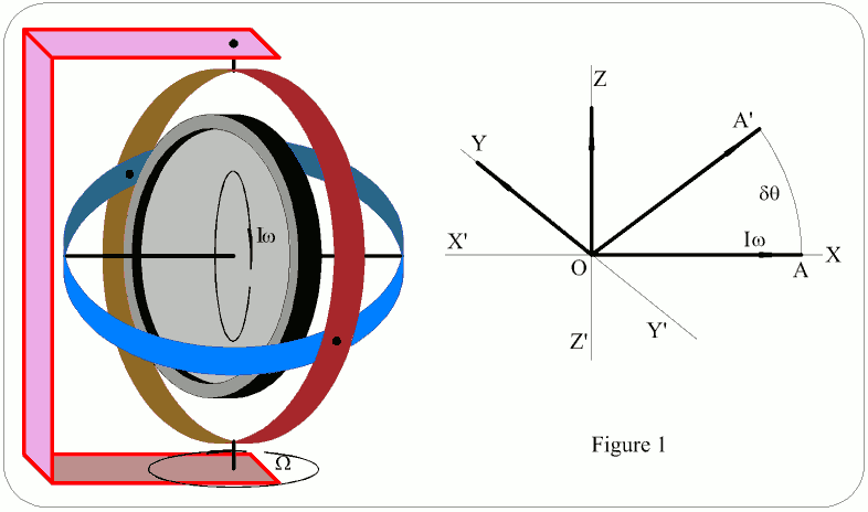
Rigidity is the ability of a freely rotating mass to maintain its plane of spin when any external force is applied to it.
First Law Of Gyroscopes: If a rotating wheel is so maintained as to be free to move about any axis passing through its centre of mass, its spin axis will remain fixed in space.
Second Law Of Gyroscopes: When a torque acts on a spinning mass with an axis perpendicular to that of spin, then the latter will precess about an axis perpendicular to both aforementioned axes, at an angular velocity, Ω, = T/Iω.
Referring to Figure 1:
Angular momentum of system = Ω Angular momentum of rotor = Iω (I = moment of inertia; ω = angular velocity) Torque = T In time δt the spin axis moves through δθ. ∴ δθ = Ωδt AA' = OAδθ = OAΩδt = IωΩδt Newton's second law states that torque = rate of change of precession, ∴ AA' / δt = T ∴ T = IΩω
This has only two planes of freedom. Springs limit the amount of precession & introduce a secondary torque. Refer to Figure 2.
The secondary torque produces a secondary precession which causes the gyro to precess in the direction of the application of the initial torque.
When the rate of secondary precession is equal to the rate of turning which produces the initial torque a state of equilibrium is reached & gyro displacement ceases.
The secondary precession is due to the initial deflection of the gyro when torque is applied, & the final displacement is proportional to the rate of displacement of the gyro.
The force exerted by the spring α extension. Extension α angle of deflection of spin axis due to primary precession. Let deflection = λ radians Spring torque = kλ (k = Hooke's constant of spring) Rate of secondary precession = spring torque / Iω At equilibrium: Rate of secondary precession = Rate of turning of gyro frame ie kλ = Iω Assuming Iω remains constant, λ α θ
The use of restraining springs produces excessive oscillation of the gyro when the initial torque is removed. The methods of damping are:
This is due to the earth's rotation.
Vertical axis: At the poles the gyro appears to precess at 15°/h in the opposite direction to the earth's rotation, & the rate decrease to 0°/h at the equator. If the latitude is φ°, apparent wander = 15° x sinφ / h
Horizontal axis: In this case apparent wander is 0 at the poles & maximum at the equator. Apparent wander = 15° x cosφ / h
This is due to bearing friction & might be greater than apparent wander in gyros of low quality. Those used for inertial guidance have no bearing friction; this is achieved by mounting the rotor in a fluid. When the gyro is running it is completely suspended in the gas & free of friction.
Wander is the drift of the gyro about the ZZ' axis. Topple is the drift about the YY' axis.
A split ring commutator is supplied with opposite phases of the vehicle power supplies. Two pickoffs are positioned in the neutral gaps of the commutator & any movement from the orthogonal position causes the pickoffs to make contact with the energised commutator. The supply from the pickoffs is used to energise a torque motor which applies a force to the outer ring & precesses the inner ring or vice versa.
Although dissimilar in appearance & construction to the rate gyro, the principle of operation is similar. The main differences are:
The primary precession, though resisted, is a continuous rotation, proportional to the rate of turn of the outer case or frame.
The gimbal does not return to the neutral position when the applied torque is removed.
When torque is applied to the frame, or outer case, a primary precession occurs & the gimbal drum rotates. Viscosity of liquid resists this precession giving secondary precession to the frame. The resisting torque due to the liquid is very nearly proportional to the rate of primary precession which is therefore proportional to the secondary precession. The integrating gyro provides an o/p angle proportional to the rate of change of i/p.
Howard's Stuff Index
Back to Pigeon's Nest
Be kind to pigeons