In 1908 Ludwig Wittgenstein (1889-1951) came to England & enrolled in Manchester University as a research student in aeronautics, which at the time was an elementary academic discipline. There he stayed for approximately two years before moving to Cambridge. Wittgenstein, with a family background in the engineering industry, arrived in Manchester after a rigid German education in the physical sciences. His aeronautics activities culminated in a patent (1910) for a unique aero-engine employing an airscrew driven by propeller-blade tip-jets. The paper also enlarged on a completely independent reappearance of his ideas some 30 years later when various types of short-lived hybrid rotorcraft emerged with rotors driven by blade tip-jets. These included the Doblhoff WNF 342 V4 (1945) & later the Fairey Rotodyne (ca 1957).
Additionally, it was postulated that by his proposed use of centrifugal flow compression Wittgenstein anticipated, although in a different physical configuration, the gas-turbine aero-engine developed during the 1930s by Frank (later Sir Frank) Whittle (FRS 1947). Professor Joseph Ernest Petavel (1873-1936) (FRS 1907), head of the Engineering Department, was an internationally acknowledged expert on the combustion of gases & is a peripheral figure in the literature with regard to Wittgenstein's stay in Manchester. It is evident that he encouraged Wittgenstein by providing a compressor from the Physics Department & also recommended him for a research studentship.
Wittgenstein is mentioned several times in the Archives of the University of Manchester (John Rylands Library). The following are typical statements: "Mr Wittgenstein came from Austria with a view to making an experimental study of aerodynamics & proposes to complete a year's residence"; "Mr Wittgenstein has continued his investigation on the rate of combustion of gaseous mixtures under high pressure". The second of these reports is dated well into Wittgenstein's stay in Manchester & it is hard to believe that Petavel did not take an interest in the combustion chamber & provide advice at this advanced stage. The importance of Petavel's work on the design of the device is emphasized in the analysis below.
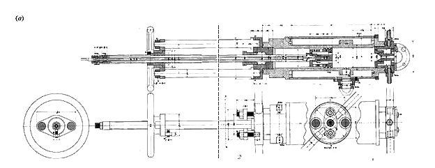
(a) Combustion chamber section & external view. The dashed vertical line shows the matched boundaries of the original drawings.
(b) Enlarged version of the right hand section of (a). Labelled components: A, main combustion chamber; B, supersonic exhaust nozzle; C, ignition port; D, piston-head mixing chamber; E, gas inlet port; F, cooling water jacket.

(c) Secondary parts & attachments. Labelled components: A, ignition device; B, valve with coolant flow; C, brass valve; D, lubricated hollow shaft.

The two drawings in figure 2a are a cross-section & an exterior view of the main assembly. The large cylindrical pressure vessel measures 1854 inches long & would have been machined from cast iron with an inner combustion chamber 3 inches in diameter surrounded by a water jacket. The water jacket is an annular volume filled with liquid water to absorb energy & reduce the inner wall temperature; it has an outside diameter of 6½ inches. The overall length of the device is approximately 38 inches, not including the piston shaft. This design has many features in common with a "small furnace" described by R. S. Hutton and J. E. Petavel, including the basic dimensions, the water-jacket design and the location and dimensions of various apertures. The drawings also have a similarity to those outlined in Petavel's published work on high-pressure machinery. The paper by Hutton and Petavel includes a photograph of a combustion unit that strongly resembles Wittgenstein's complete system as shown in figure 2a. The dimensions marked on Wittgenstein's drawings match those indicated in Hutton and Petavei's paper so closely that it is reasonable to suppose that some exterior fittings may have been copied or adapted; at the very least it seems likely that instrumentation could have been common to both devices.
The main functional components of the design are labelled in an expanded view in figure 2b. Inside the main chamber a sliding piston arrangement varies the volume of the combustion zone at the top of the cylinder; this is achieved by rotating the circular handle located al the far end of the device. A similar mechanism had been employed by Petavel to feed carbon rods into electric furnaces. The piston has a hollow shaft with a valve that allows fuel to be introduced into a space behind the piston through several small radial holes. The diameter of these holes has not been dimensioned on the drawing, and it might have been that the piston head was replaceable so that the diameter could be varied. The maximum capacity of the main chamber is approximately 85 cubic inches using this piston head. The annular volume within the piston head forms a pre-combustion mixing chamber with a volume of approximately 6 cubic inches. Two radial ports of different sizes are shown at the lower end of the main chamber beneath the water jacket, permitting two different gases to be supplied; one of the gases would have been compressed air. No equipment is shown on any of the drawings for pumping the fuel. The fuel-air mixture is then introduced into the main combustion chamber through an annular gap in the piston head. The mixture would probably be ignited in the chamber by using an electric arc at the side of the combustion chamber; details of the ignition device are shown on the supplementary drawings. Had Wittgenstein proceeded with his project electric spark ignition would almost certainly have been used for an aero-engine configuration.
The most distinctive addition to the basic chamber design is a simple water-cooled supersonic exhaust nozzle of the de Laval type 2½ inches in length situated at the top of the chamber. The emerging jet of hot combustion products could be used for thrust measurements and thus for the development of exit nozzle geometries required for small combustion chambers fixed to propeller-blade tips.
A more straightforward adaptation would be to feed the hub of a hollow-bladed propeller directly to repulsion jets on the blade tips. The nozzle is simple to change because it is screwed into the chamber & restrained with a bolted flange. Cooling water circulates around the nozzle through the two radial hose fittings shown at the top of the drawing. An additional feature of Wittgenstein's design is two radial bars that are sketched at each end of the main chamber in the exterior view. These would probably connect to a restraining structure within the laboratory. With the chamber mounted vertically, & the exhaust facing upwards as shown, the exchange of nozzles could take place without significant water leakage. In this configuration the resulting force on the apparatus & the supports would have been in the downward direction.
The drawings labelled in figure 2c represent some secondary components of the system. Further additional components would be required for operation of the complete unit, but these may already have existed & additional drawings may not have been required. The dimensions of the external thread of the part on the left-hand side of this drawing (1-inch Gas) are the correct size for it to be screwed into the radial port in the main combustion chamber above the piston. Its hollow cross-section forms a steel cylindrical side passage, probably designed to contain the ignition device, or plug. the latter fashioned from a cylinder of insulating material, such as ivory or ceramic, with a steel spindle core. The design allows the insulation for the ignition plug to be restrained in compression & seems to owe its form to earlier work by Petavel. Petavel explained that this configuration was needed to compensate for the brittleness of the insulating materials available at the time. The spindle's end would form one of the electrical poles & ignition could be achieved by an arc created within the main chamber, or by fusion of a thin wire attached to the spindle. The inner section is removable by unscrewing the circular handle to allow replacement of the terminal piece without breaching the water jacket. A small threaded part, without dimensions, is sketched protruding through the handle; this could be the external terminal of the ignition plug. The terminal would connect to a power supply, & the electrical circuit would be completed by attaching the other end to the casing of the chamber. Similar ignition plugs were used later by W. Bone et al. The overall length of this piece is approximately 12 inches.
The drawing in the centre of figure 2c illustrates a steel assembly bolted to a base plate. A valve regulates fluid flow through a hollow tube held in place by a three-way brass connector screwed to the base of the assembly. The connector allows a second fluid (probably a coolant) to circulate around the tube. Some dimensions are missing (for example those for the base plate) & it is difficult to relate the overall function of this component to the main assembly of figure 2a. The partial assembly measures approximately 10½ inches long, not including the shaft.
At the right of figure 2c is a simple steel valve that would have been used to regulate gas flow into the chamber at the rear of the piston; the drawing lacks a seal. The steel component measures 5¼ inches in length. The drawing at the top right of this figure shows a brass part, 4 inches long, with ports for the lubrication of a sliding hollow shaft. The function of this part is unknown because the dimension of the main external thread (approximately 1½ inches Gas) does not match the internal thread on any of the remaining parts.
The complete device is suitable for combustion experiments with pressurized gas mixtures & would have been able to operate in this configuration. For a given fuel-air mixture, movement of the piston varies the main chamber volume & thus the pressure during combustion. The internal shape of the nozzle for optimal thrust is governed by the pressure difference between the combustion chamber & the outside atmosphere.
Comment has on the whole been unfavourable; for example, an engineering friend of Mays (with some hindsight) complains, "why ... all this trouble - could he [Wittgenstein] not have made a gas jet to push an aeroplane through the air in the way modern jets do?" The friend argues that it is inefficient to power a propeller in this manner; that is, by converting the momentum of a gas into the rotational energy of a propeller. However, one can apply what amounts to an engineering topological transformation to the engine, making the propeller synonymous with the compressor in a centrifugal-flow gas turbine. The transformation can be taken one step further: the exhaust gases from the turbine mighty be used to drive an additional turbine mounted on the main rotating shaft (a small residual thrust remaining). The shaft is connected to a propeller by means of reduction gearing. The resulting turbo-prop engine is well known to be very efficient when used in lower-speed, low-altitude aircraft, & is a proven example of "powering a propeller by the momentum of a gas".
One article (translated here from the German) that discusses Wittgenstein's patent in greater technological detail confirms & adds to points made previously. It notes that the patent does not specify Wittgenstein's ideas, if any, for an ignition system. It regards as "unclear whether a real demonstration model was ever built". It goes on to state: [The centrifugal forces have to be such that] the pressure of the compressed air as well as the pressure in the fuel line is greater than the combustion pressure [thus avoiding flashback]. To successfully [use centrifugal forces] as a feed pump the dense fuel can be accepted. However ... the much lighter air [would only be sufficiently compressed] if the propeller rotated at speeds giving rise to blade tip velocities substantially above the sonic velocity.
Note that comparable tip-jet schemes in later aircraft pump the fuel to the blade-tip-mounted combustion chambers & use a compressor for the air. (A high centrifugal acceleration is required for the compression of air.) Other problems noted include inadequate requisite performance of then available compressor(s) - pressure tight mountings into the propeller blades having to cope with hot gases emerging from a centrally mounted combustion chamber [as opposed to blade tip combustion], an unachievable requirement since the technology pertaining to the strength & heat resistance of materials was not available at the time & was not to be resolved for several decades.
Despite these insoluble problems, the scheme was considered by the article's authors to be "fundamentally ingenious", as indeed it was in about 1909.
In a letter addressed to Wittgenstein, one of his old Linz schoolmasters resuming contact in 1915 asked, "Was ist aus der Flugmaschine geworden?" ["What became of the flying machine?"] At school Wittgenstein had shown a particular interest in aeronautics. The enquirer may have been unaware of Wittgenstein's change of vocation from aeronautical engineering to analytical philosophy. The answer is that Ludwig's innovative design was never to be completed. His researches at Manchester never progressed beyond the construction of the "variable volume combustion chamber" & using it to optimize exit-jet nozzle geometries.
The role of Professor Petavel as his supervisor has been emphasized here. Design features of combustion chambers incorporated in Petavel's considerable researches in this area are reflected in the construction details of Wittgenstein's chamber (although Ludwig gets no mention in an extremely comprehensive 8000-word obituary of Petavel as having been a research student in Petavel's Engineering Department). Biographies, large or small, of Wittgenstein always include the Manchester period, & some philosophy academics have related Wittgenstein's involvement with aeronautical engineering to their own interpretations of his philosophical works.
Wittgenstein's combustion research was conducted a century ago when the technology was immature. He faced formidable problems, some of which would not be solved for many years. If he had persevered with what was a complex & difficult exercise & even achieved a measure of success as the necessary supporting technology caught up with his requirements, the emergence of more conventional aero-engines accelerated by the demands of World War I would have more than improved on anything he had to offer. Still, as described previously, the basic idea of tip-jet-driven propellers found an application in hybrid rotorcraft developed many years later & are even being revived today.
Howard's Stuff Index
Back to Pigeon's Nest
Be kind to pigeons
![]()