The MCP61SM-AM (and its relative the MCP61PM-AM) is a Foxconn / ECS motherboard which is used in various Gateway, Acer, Packard Bell and the like PCs. It supports Socket AM2 processors and DDR2 RAM. There is nothing particularly outstanding about it (it is rumoured to be able to take 125W AM3 CPUs without blowing up, but I don't know if they run at full speed or even if it is true at all), but equally there is nothing particularly shit about it and it is a perfectly competent motherboard for a boggo domestic PC.
Because of this, and because of the large number of "different" PCs it was used in, there seem to be a lot of them about. People get hold of them second hand and put them into their own cases. They then go on the internet to try and find out what the pinout of the front panel connector is.
Everything else about the board is standard and/or labelled so there is no confusion. The front panel connector, however, is not labelled at all. This wouldn't be a problem if there were manuals available. Unfortunately there are not. There are several widely-quoted links to the Foxconn, Gateway, Acer etc. websites which purport to refer to manuals available for download, but none of them fucking work. Whether this is because the manuals are no longer on those websites at all, or just that the websites are run by the all-too-common variety of cunts who insist on making any link into the site from outside redirect to the front page, I don't know, and in most cases the website's search function to find such manuals doesn't fucking work either so I can't find out. Not that it makes much difference; the point is that regardless of which particular variety of shit is to blame for the situation, the manuals aren't there.
Occasionally a link turns up that does work and leads to a manual for a similar motherboard with an almost-but-not-quite-the-same model number, but all such that I have found have a different front panel connector - a 10-position header, whereas the MCP61SM-AM has a 14-position header. So this is no good either.
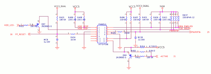
Fortunately, after a good deal of searching, I did manage to locate a copy of the schematic manual for the MCP61PM-AM. This board has the same 14-pin header as the SM version, and from the schematic it is possible to work out what the pin assignments are.
The labels on that diagram are not the most helpful in the world, so here is what it works out to in English:
| MCP61 Front Panel Connector Pin Numbering | |
|---|---|
| 1 | 2 |
| 3 | 4 |
| 5 | 6 |
| 7 | 8 |
| 9 | 10 |
| 11 | 12 |
| 13 | 14 |
| MCP61 Front Panel Connector Pin Assignments | |
|---|---|
| HDD LED + | Power LED + |
| HDD LED - | Power LED - |
| Reset button - | Power button + |
| Reset button + | Power button - |
| Not used | No pin |
| Not used | Active LED + |
| Not used | Active LED - |
The "Active" LED is controlled by the onboard ethernet interface, and indicates whether there is a working ethernet connection present. Not entirely sure why they want to indicate this on the front panel but never mind, it's another pretty light.
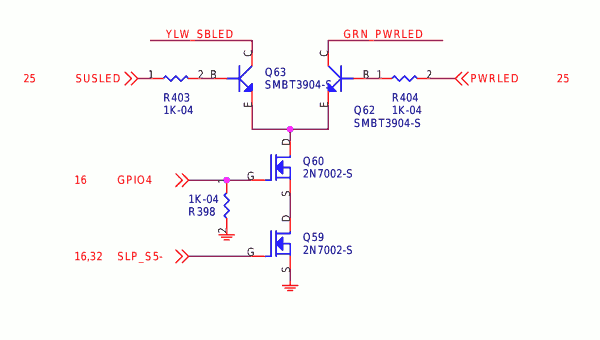
The Power LED function is a bit fancy, although you'd never know it from just wiring up an LED with + to pin 2 and - to pin 4 as in the above table. Normally, pin 2 stays high, and pin 4 is pulled low when the machine is switched on. BUT... it is also possible for pin 4 to remain high and pin 2 to be pulled low, as is shown by this part of the circuit diagram:

It looks like it's supposed to drive one of those two-colour LEDs which consist of two LED chips in inverse parallel in the same package, and make it light up green for "power on" and yellow for "standby". This would explain the "PWRLED" and "SBLED" labels on the lines. For some reason, though, mine doesn't seem to do this - I've pissed around with it and pin 2 remains high at all times. I dunno. Maybe what I think of as "standby" - ie. the state in which the motherboard is powered down apart from the circuitry necessary to detect the power button being pressed, which is what "standby" means for TVs and shit - is not what they think of as "standby"; maybe they are thinking of what you get when you tell it to "suspend" instead of to "shut down" (the drive circuit diagram does label its control line "SUSLED" after all). I never do that and I don't have an OS on the box with this board in it at the moment (because the hard drive I was going to install one on was fucked when it was delivered) so I haven't tried that.
Stephan Hubers writes:
[...the "SBLED" LED is] the LED that tells the user whether or not the system is in SUSPEND-mode. Since, when you "suspend" the system, the POWER-LED will be turned off. In most Packard-Bell housings they use a bi-color LED to indicate the state of the computer: BLUE for power-on and YELLOW for suspend.

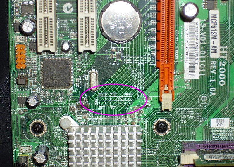
Perhaps the oddest thing about this whole business is that the pinout for the front panel connector is labelled on the board; it's just that no fucker can find it. I don't know why since it's not particularly inconspicuous, but you can't see it if you're looking for it. You can only see it once you've farted around for ages trying to find the information elsewhere. That is what happened to me and that is also what seems to have happened to all the people who have been looking on the internet and asking what the pinout is. I suppose it is some kind of quantum effect. Anyway, here is a photo of it.

Back to Pigeon's Nest
Be kind to pigeons