In among my piles of junk I have a large quantity of these things. I am not sure why.
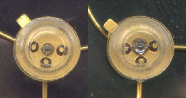
The one on the left is a Honeywell SE4355-002, if the writing on the bag of them is correct - there are no markings whatsoever on the thing itself. It appears to be a very shit red LED. When you put volts on it, it lights up red. Very dim red. So dim, in fact, as to be fucking useless. I can't find a datasheet for it anywhere on the internet, but I have managed to find a couple of sort of official pages about it which give its peak emission wavelength as 660nm - ie. visible red. So this sort of confirms that it is an extremely shit visible red LED.

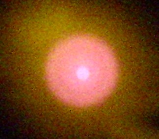
However, these same pages also describe it not as a red LED but as an IR emitter, and when you take a photo of it with a digital camera it comes out not as a red light so dim you can hardly see it, but as a big purple splotch. So I figure it is actually a wideband IR emitter and the "peak wavelength = 660nm" thing is bollocks. Maybe it means 880nm but whoever originally typed it was a blind git who couldn't tell the difference between an 8 and a 6 and the mistake has just been repeated all over the place, rather like the thing about spinach having loads of iron in it is actually bollocks and people say it because some bugger got a decimal point in the wrong place like bleeding ages ago and everyone else has just copied the mistake.
The one on the right also has no markings whatsoever on the thing itself, but it doesn't have anything written on the bag it's in either. Because it looks the same, I initially thought it was the same, so I put volts on it and then wondered why it didn't light up. But then I looked closer and discovered that it doesn't look quite the same if you look hard enough - the chip is slightly bigger, although it's bloody hard to notice, and it has 3 connections instead of 2, which is even harder to notice. So I thought "ah, it must be a phototransistor then", and started trying to measure it.

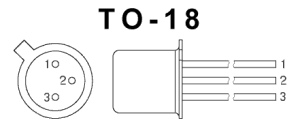
It looks like a standard TO-18 package, as shown on the right, except with a transparent plastic lid instead of being all metal. But it doesn't seem to have the standard TO-18 transistor pinout. Normally you would expect 1 = emitter, 2 = base, 3 = collector. Measuring diode drops between the pins of this thing it looked like 3 = emitter, 2 = collector, 1 = base. Weird. I stuck it on an hFE meter and it said the hFE was 923, which is remarkably high. Also weird. Maybe it's a Darlington, only it doesn't have two diode drops between base and emitter like you'd expect. Or maybe its photo-response is buggering the meter up... put thumb over it... reading does not change... OK, maybe it's just fucking weird then.
So I tried connecting it into a standard phototransistor transimpedance amplifier circuit with an op-amp. You know the one. Big-ass feedback resistor from output to inverting input, device collector to inverting input, device emitter to ground, base left open, non-inverting input grounded. Then I shone a TV remote control at it while observing the op-amp output with an oscilloscope. OK, yes, it worked. It was fucking shit though. I had to hold the remote control within about 2 inches of it to get any kind of decent output. I could probably get just as good a result from a 1N4148. (tries it) Slight exaggeration, but not all that much.
I pissed around with the amplifier configuration a bit trying to make it more sensitive, but without useful result. No matter what I did it remained shit. This pissed me off, because I had had an idea for a gadget which involved detecting modulated IR emissions and so having a big bag of IR phototransistors to play with was very handy. Particularly since these things seem to have a very narrow acceptance angle which was just what I wanted. Except it wasn't handy at all because they were so shit that they weren't any use. I was planning to use them with a PIC16HV753 using its built-in op-amp to amplify them, but I would have needed another gain stage to get a usable output because they were so crap, and there wasn't room for one because the gadget was intended to fit in a very small space indeed. So that idea was fucked.
So I started buggering around on the internet looking for IR photodiodes or phototransistors with narrow acceptance angles that would not be shit. These are actually quite rare. Most IR detectors are intended for applications where things are supposed to work without arsing around trying to line things up, so they have very broad acceptance angles. My gadget was supposed to tell whether it could detect IR from a very circumscribed area or not, without being confused by spurious reflections from things around it, so a broad acceptance angle was exactly what I didn't want. Therefore the amount of buggering around I had to do was quite large.

In the course of said buggering about I happened across a listing for the Honeywell SD5600-001. This is not a straight phototransistor or photodiode, but it had been mis-listed as if it was, and since it does have a narrow acceptance angle my search for photodiodes with narrow acceptance angles threw it up.
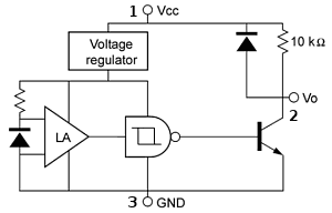
My immediate thought was "arse, it's not a photodiode", and I was about to move on when I thought "hey, just a minute..." The diagram on the right maps to the TO-18 pinout as 3 = GND, 2 = Vo, 1 = Vcc. Comparing this to what I thought I'd measured (ie. 3 = emitter, 2 = collector, 1 = base) it can be seen that 3 and 2 are an emitter and a collector, and 1 can... er, well, sort of get to the base somehow, depending on exactly what circuitry is hidden behind the symbols and exactly how it conducts/leaks. So I tried wiring one of my thingies up like that - 1 to +12V, 3 to ground, 2 to the oscilloscope, and no other components at all.
Fuck me! It works. I can shine the TV remote control at it from any distance up to a foot or so and as long as I am on axis I get full-amplitude square pulses out of it. So that's what the bastard is! Like the SD5600-001, it is a photodiode and amplifier and Schmitt trigger all in the same package. I still have no idea what its actual type number is but since all you can do with it is put volts and IR in and get square pulses out and I have found out how to do that, it doesn't matter very much.
It is odd, though, given how the way I got these things in the same bag in the same lot of junk implies that the original intention of whoever put them in there was to use them together as transmitter/receiver pairs, that the SE4355-002 seems to be very poorly matched to the peak sensitivity wavelength of the detector thingy. The LED in the TV remote control is a much better match. While the SE4355-002 will trigger the detector, it needs to be within a centimetre or less to do it, and shining directly at the detector too. Trying to make it work off reflections, even specular reflections at very close range, I can't get a bloody thing out of it. But the TV remote control, which does not emit any visible light at all, will easily trigger it off diffuse reflection at a few inches range.
Diffuse reflection of the spot of an 808nm 500mW laser will trigger it merely by being somewhere in the vicinity, but then that isn't really all that surprising.
So there we have it. I'm not really sure what the point of this page is, but I guess that if you too have some unmarked devices which appear to be shit phototransistors with a weird pinout and reading this page inspires you to try them as Schmitt-output amplified photodetectors and they turn out to work like that, it will have had some point.
More rather pointless information: The photo of the SE4355-002 operating was taken with a shitey compact digital camera which refuses to focus by itself and cannot be focussed manually. It looked OK on the preview screen but the version of that image that is actually captured when the button is pressed is completely arse. I don't know why, and the manual for the camera is totally fucking useless. The photo of the two devices at the head of the article is actually a scan from an Epson V200 at 4800dpi, which makes quite a good microscope. I couldn't use the same method to make an image of the device in operation because it won't scan with the light off and I can't be arsed to modify it so it does.
Back to Pigeon's Nest
Be kind to pigeons