Hydrostatic transmission for road vehicles has low losses at high speeds
This is an article from "Design Engineering" magazine, November 1989 issue. The system it
describes is most interesting, but unfortunately doesn't seem to be in development or
production anywhere now as far as I can find out.
Note: If you were looking for information on hydraulic brakes, see
Howard's article How Car Brakes Work.
Article begins
Hydrostatic transmission for road vehicles
has low losses at high speeds
Variable displacement hydrostatic machines offer solutions to the
problems encountered in vehicle transmission systems. Research at
the University of Edinburgh, described by M J Rea and S H
Salter of the Department of Mechanical Engineering, has
centred on improving the efficiency and reducing the noise of axial
piston hydraulic machines.
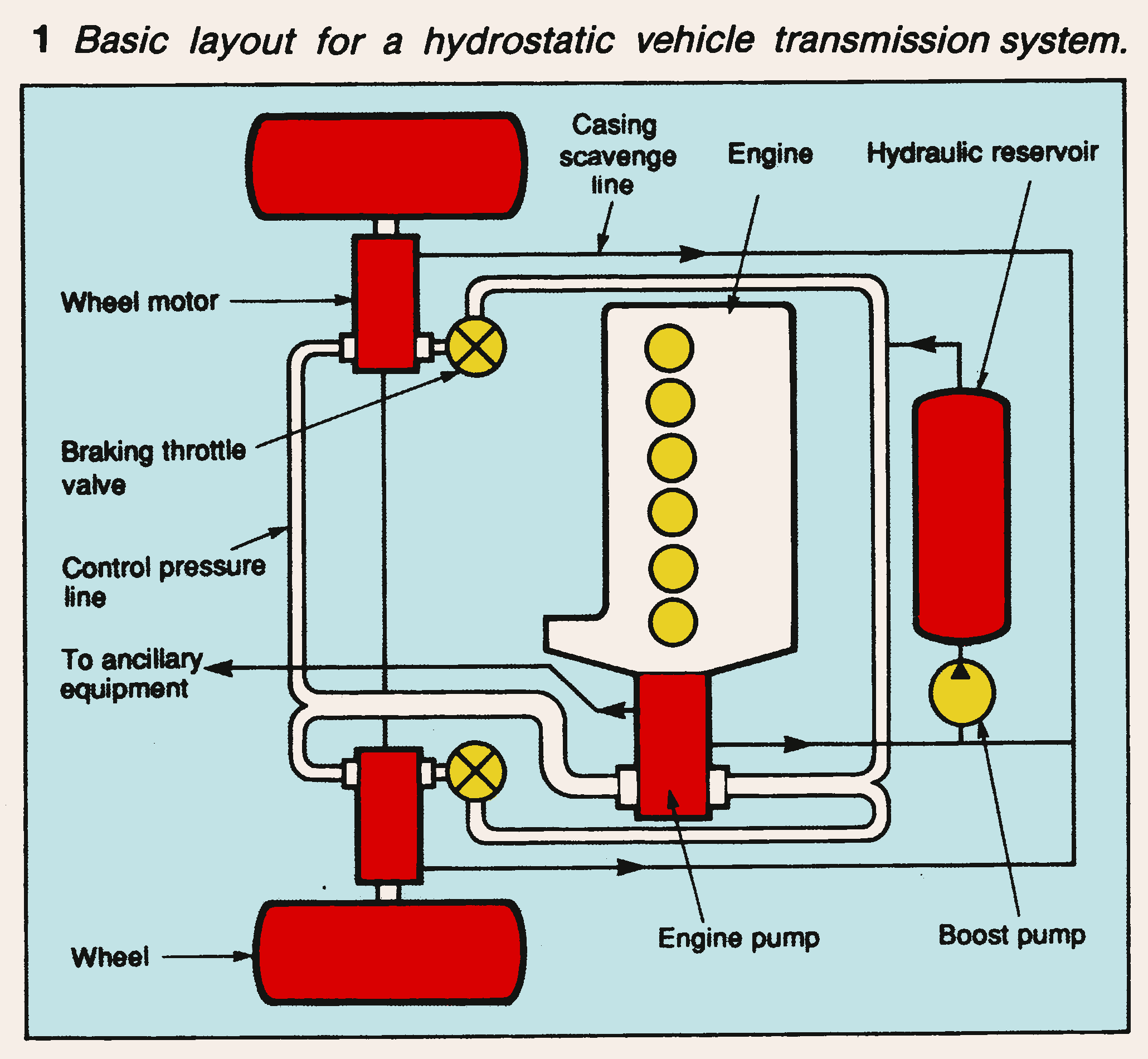
The basic layout for a hydrostatic vehicle transmission is shown in
Fig 1. The engine is directly connected to a variable displacement pump.
Hydraulic pipes connect the pump to two or more variable displacement
wheel motors. A pressurised reservoir allows for temperature expansion and
make-up of leakage. The throttle valves are used to provide hydraulic
braking.
The principal advantage of the system is the infinitely-variable
transmission-ratio between the engine and the wheels. This enables the engine
design to be optimised for maximum fuel economy and attention to exhaust
emissions rather than the emphasis on a smooth torque against speed characteristic.
It becomes possible for the transmission system rather than the
carburettor throttle to be used as the primary way of controlling the engine power.
The engine of an accelerating hydrostatic vehicle would be able to rotate at
peak power continuously while the transmission adjusted the wheel
torque. At the cruising speed, the transmission would force the engine to
a lower speed and so lower the power developed.
Other advantages over mechanical systems are that hydraulic power is
carried in pipes so there are few restrictions to the relative
orientation of the engine and wheel motors. This
Ieaves the vehicle designer more freedom to position the major components.
Power steering and a hydraulic suspension system could be
run directly from the main system. Extra wheel motors could provide four
wheel drive. A regenerative braking system is dependent on an efficient
infinitely variable gearbox. An additional pump/motor connected into the
hydraulics and driving an energy store flywheel would provide dramatic
acceleration and improve urban fuel economy.
Sizing hydraulic transmission components
A system such as that shown in Fig 1 should be designed to deliver maximum
power to the wheels over as large a range of speeds as possible. The power
throughput is the product of the
pressure and the flow. The ratio of the speeds of pump and the motor would
be equal to the ratio of their displacements.
An efficient transmission system on a vehicle requires careful sizing
of the various hydraulic components. The engine-pump would be matched to
develop maximum pressure and flow at the engine's maximum power. The
wheel motor is required to deliver full power over a broad range of
speeds. To avoid over-sizing this means that it is necessary for the
machine to be able to run over the rated speed at reduced stroke. The
motor size required for a particular vehicle would be determined
by the full pressure full stroke torque required at low vehicle speeds and its
capacity to run over the rated speed.
Hydraulic machines have high internal loads opposed by large bearings and are
not designed to run in overspeed conditions. Manufacturers advise that the
pressures be reduced as well as stroke causing the power to drop below rated
peak. The Clerk machine developed at the University of Edinburgh has been
specifically designed to run at three times the rated speed for use in
hydrostatic transmissions.
Losses in hydraulic machines
A hydrostatic transmission involves conversion of power between mechanical
energy and hydraulic pressure. The overall system efficiency is the
product of the efficiencies of the pump and the motor. Pumps and motors with
conversion efficiencies of 90% will lead to a transmission system
losing a fifth of its power throughput. For a successful vehicle
transmission system it is not tolerable to have an individual machine
with losses higher than 5% of throughput.
Trilink pump
The research team built an experimental hydraulic machine based on a
design by Robert Clerk to investigate ways of reducing losses. Fig 2
shows a cross-section of the machine. The principal improvements over existing
designs are as follows.
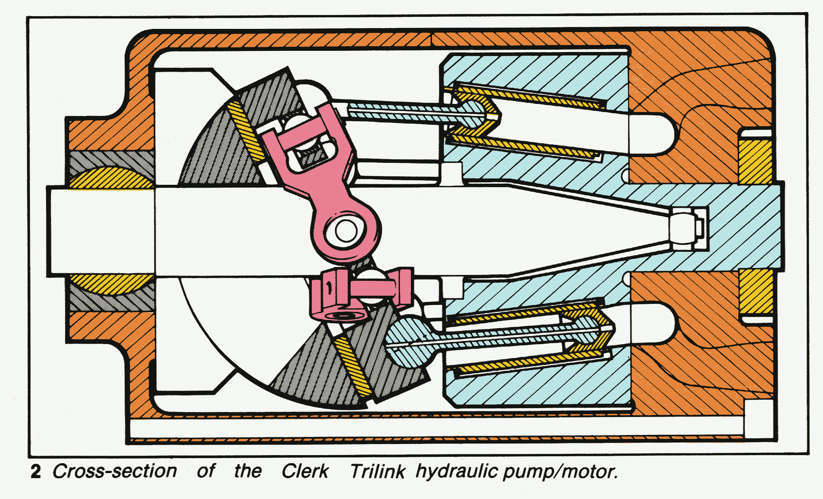
The Trilink machine makes extensive use of hydrostatic bearings. In a
hydraulic machine the principal loads are due to oil pressure acting on
components. It is possible to oppose a load with a hydrostatic bearing of
Iarger area fed by the pressure that causes the initial load.
The impedances give the bearings stiffness and set the running clearances.
All moving parts are supported on hydrostatic bearings with the
exception of the little ends and Trilink bearings that have limited excursions
and alternating loads so they can be supported by spherical squeeze film
bearings.
The geometry of individual bearings involves a design compromise between
Iow shear losses or low leakage losses. A computer model was used to minimise
the combined shear and leakage Iosses at the machines operating speed.
Large hydrostatic bearings require surfaces that remain flat to within
10-20 microns despite varying loads and temperatures. The research team developed
a number of locating techniques for permitting the bearing support
structure to distort while the running surfaces stayed within tolerances. As
aIl bearings are actively fed the casing is pumped dry of oil so the
machine has no churning loss.
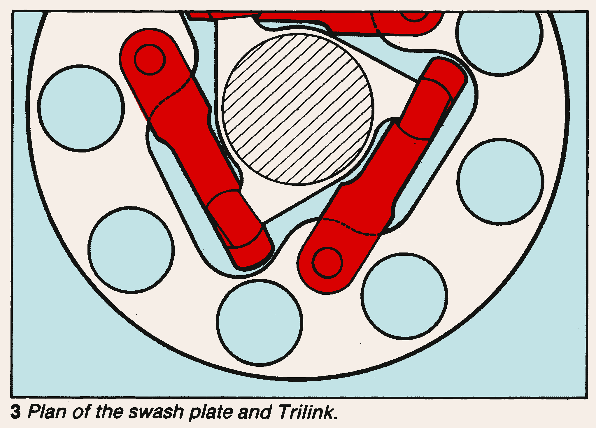
Torque to the swash-plate is carried
by a mechanism known as the Trilink. The swash-plate is coupled to the
mainshaft by three spherically ended links that cary all of the torsional
Ioads, Fig 3. Conventional slipper-pad pumps transmit torque through the
hydraulic pistons.The resulting friction as the piston is forced against the
cylinder wall is a major cause of power loss and wear. The Trilink allows the
Clerk machine to run at larger angles
and higher pressures so having a greater power throughput than conventional
machines of the same size and weight.
Oil has a finite bulk modulus. It is convenient to consider it as
storing the equivalent of around 1% of the pumped energy at 200 bar.
While 500W on a machine developing 50kW is not a great loss in terms
of efficiency it is very significant if even a fraction is dissipated
as noise.The Clerk machine has adjustable port face timing that enables
continuous equalisation between the pressure in the port and the cylinder
whilst the machine is running.
Many hydraulic machines require
high boost pressures to overcome the static head losses caused by oil
circulation in restricted passageways. Breathing losses increase with the
cube of velocity so can become very significant when a hydraulic machine
runs over the rated speed. The primary oil circulation was designed to avoid
abrupt changes in direction and create a hydraulically smooth flow for
the oil passing through the machine.
The machine was tested to investigate the shear lossesat high speed. The shear
losses amounted to 6kW corresponding to 1.6% losses at full pressure power.
Leakage from the hydrostatic bearings was measured and found to correspond well
with the theoretical model, amounting to less than the shear
losses.
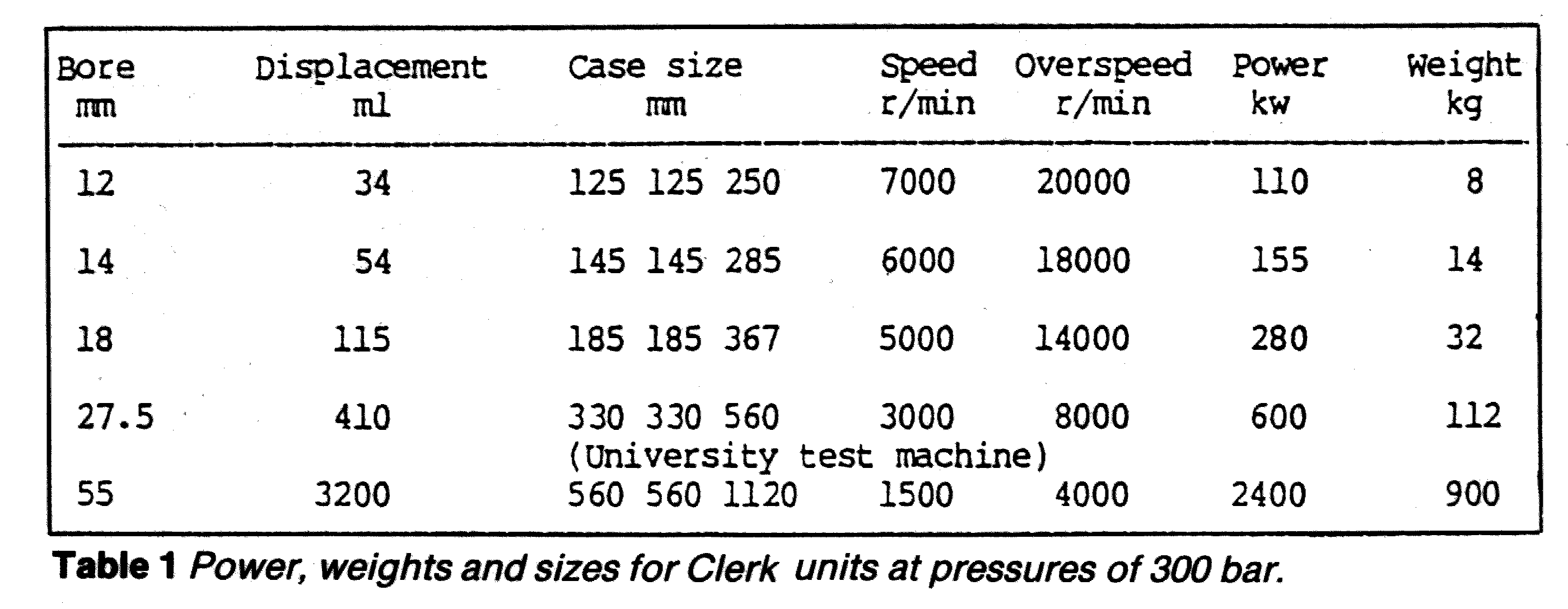
Table 1 gives examples of automotive power machines in comparison to the
machine tested at the University.
The Clerk Trilink pump offers a
significant improvement in the performance of axial piston hydraulic
machines. Extensive use of hydrostatic bearings permits the machine to
run at three times the rated speed, so making it ideal for hydrostatic
transmissions. The use of a controllable transmission system would
have a dramatic effect on fuel economy and vehicle
performance.
Acknowledgements
The work carried out at the University of Edinburgh was supported by SERC,
Commercial Hydraulics and Mac Taggart Scott. The project requires
further commercial support to continue the test programme. This paper will be
presented to the AutoTech Congress, 14-17 November at the NEC
Birmingham. Full details of the Congress from Julie Brown, IMechE,
Tel. 01-2227899.
Article ends
Back to Pigeon's Nest
Be kind to pigeons
![]()