Note: see here for JTAG via the parallel port, but read this section as well.
The Aztech DSL600E, or the Solwise SAR-600E, which is the same thing, has two JTAG ports, one "plain" JTAG and one EJTAG. This is because the TNETD7300 has a MIPS core for general processing and a separate DSP core to deal with the ADSL interface, and TI have been too spazzy to chain their JTAG interfaces onto one port. For some reason no bugger even mentions that it has two JTAG ports, so when you check out the circuit and find that it does, it is not obvious what is going on. The answer is that there is a separate port for each core. This page is about connecting to the EJTAG port, which is the one relating to the MIPS core.
Wankers like routertech.org spaz on about the incredible difficulty of talking to the device via JTAG as if it was nearly as hard a task as the Manhattan Project designing the first ever implosion system by hand calculation. This is bollocks, and stupid bollocks at that. JTAG is an industry standard which is used all over the place by actual real engineers to do serious things which are a whole fuck load more complicated than simply reading and writing blocks of memory, which is what we are concerned with here. It's only "difficult" because most of the references to it on the internet are dickheads whining about it and there is next to fuck all actual useful information among all the noise. The only really awkward bits are figuring out which of the two ports to use (use the EJTAG one) and what the connections are (see below), and it would be a lot more useful if the silly fuckers would just provide this information instead of wittering on about how hard it is when it isn't.
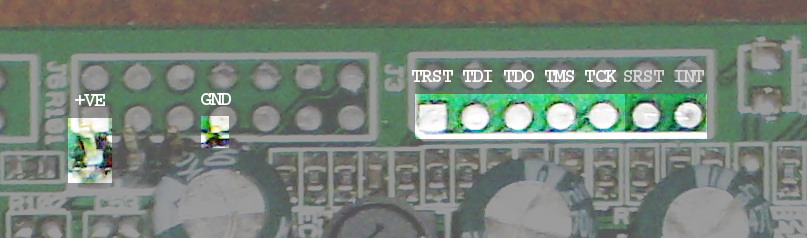
The ports are connected to headers on the PCB, in theory, only they aren't actually there. The pads are there, but they do not have headers soldered into them. Unfortunately, they do have the solder. This means it is a pain in the arse to do a pukka job of installing the headers because you have to clean every scrap of solder out of the plated-through holes which are barely big enough to take the header pins even without any adhering solder. It seems to be that shitey-arsed lead-free crap, as well, which makes it worse. I decided I couldn't be arsed and pretended the headers were surface-mount parts and just soldered them to the top of the pads.
It could be worse, though, because you don't need to install the whole 14 pins; you only need to install one 7-pin strip, so there is no problem with the front 7 pins of a dual-row header getting in the way of soldering the rear 7 pins or any shit like that. Because the pinout is non-standard and what should be the +3V3 pin is actually grounded, you have to pick that up from elsewhere in any case; the serial port header, which is already installed, is convenient. So you might as well pick ground up from there as well and cut the cackle. Below are shown the various points to which connection needs to be made (see also this page).
As is usually the case with clocked serial interfaces (cf. programming serial RAMs or programming PICs), a parallel-port adaptor is the best way to do it. So I ordered a D25 connector to make one with, having all the other necessary bits already. But this fell victim to the same dead and chewed protulism that has affected various other items connected with this project: taking so ridiculously fucking long to arrive from China that I got fed up waiting and did it some other way instead. What the fuck is it with stuff taking so long to arrive from China? So much of the time it would have been delivered more quickly by someone bicycling the whole distance, but when it eventually does arrive it turns out that it has actually travelled on a fucking plane. What the pissing fuck is the point of using a shitty, expensive, grossly fuel-inefficient method of transport whose only advantage is speed, and then completely wiping out that advantage by leaving the fucking package sat in a shed somewhere for months? If it's coming on a plane it ought to arrive within a few days of being ordered. Otherwise there's no fucking point using a plane. If it's going to take bleeding forever to arrive, then send it on a fucking ship for fuck's sake and stop being so fucking futilely wasteful.
The D25 connector did arrive eventually and its use is described later on. But by that time I had already got everything working by other methods.
I bought something calling itself an Altera USB Blaster off Amazon for a fiver. I don't think it's a real one. It seems to show evidence of being a wonky piece of shit. And I don't know why it has such a silly name. It is true neither literally (it doesn't blast anything, it's an interface box, not a mining explosive) nor metaphorically (it is as slow as gluey shit). But it does sort of work. It is necessary to connect it to the target board with a minor nest of jumpers because the pinouts don't match. I used this stuff, which is dead handy for this sort of shit. The pinout of the plug on the end of the ribbon cable which this gadget uses to connect to the target, viewed from the underside of the plug (ie. the side with the holes in it), is like this:

urjtag does not seem to care about the ~TRST and ~SRST signals, so those can be left unconnected. It is however necessary to make a jumper to pull ~TRST high, otherwise fuck all happens. This is just a resistor (anything between 100 ohms and 1k should work) from ~TRST to +ve.
To make the blaster thing work as a normal user, rather than as root, create a file /etc/udev/rules.d/90-altera.rules which contains:
SUBSYSTEMS=="usb", ATTR{idVendor}=="09fb", ATTR{idProduct}=="6001", MODE="0666"
then restart udev.
I used urjtag, which is currently at version 0.10+r2007-1.2 in Debian, to talk to it. This did weird things. Simply installing the binary from the Debian repository didn't work - detect just hung and didn't do anything. Compiling it locally from the Debian source was more successful; it produced a bit of output and then hung. After running it again and again it eventually worked even though I hadn't changed anything. Fucksake. I am inclined to blame the cheap-ass blaster thing for being a wonky piece of shit. I think the software is a bit wonky too but suspect it would probably be OK if the whatsit really was what it says it is.
This is what is called dead cat syndrome. I once installed a second-hand Honda C90 engine which would not fucking start even though it had fuel and a spark and everything and there seemed to be no reason at all why it shouldn't go, except that it had been colonised by invisible dead cats. So I did some speed and stood there kicking the fucking thing over for two hours straight to chase the furry little bastards out of it, and eventually it fired and was perfectly fine after that. (Unlike my shoe which now had a hole in it and was letting in water.) You don't normally expect to find dead cats gumming up the works of electronic things, especially not brand new ones, but it seems that they breed them differently in China.
To save having to tell the software what sort of cable I was using every time I fired it up, I made a file ~/.jtag/rc containing:
cable usbblaster
Anyway, what you SHOULD get, once the lurching furry fuckers are all out of the way, is something like the following. This is a transcript of a session which reads the entire EPROM contents and dumps it to a file /tmp/xxx.
$ jtag UrJTAG 0.10 #2007 Copyright (C) 2002, 2003 ETC s.r.o. Copyright (C) 2007, 2008, 2009 Kolja Waschk and the respective authors UrJTAG is free software, covered by the GNU General Public License, and you are welcome to change it and/or distribute copies of it under certain conditions. There is absolutely no warranty for UrJTAG. warning: UrJTAG may damage your hardware! Type "quit" to exit, "help" for help. Connected to libftdi driver. jtag> detect IR length: 5 Chain length: 1 Device Id: 00000000000000000001000000001111 (0x0000100F) Manufacturer: Hitachi (0x00F) Part(0): AR7300 (0x001) Stepping: 0 Filename: /usr/share/urjtag/hitachi/ar7300/ar7300 ImpCode=01000001010000000100000000000000 41404000 EJTAG version: 2.6 EJTAG Implementation flags: R4k DINTsup ASID_8 NoDMA MIPS32 Processor entered Debug Mode. jtag> detectflash 0x30000000 Query identification string: Primary Algorithm Command Set and Control Interface ID Code: 0x0003 (Intel Standard Command Set) Alternate Algorithm Command Set and Control Interface ID Code: 0x0000 (null) Query system interface information: Vcc Logic Supply Minimum Write/Erase or Write voltage: 2700 mV Vcc Logic Supply Maximum Write/Erase or Write voltage: 3600 mV Vpp [Programming] Supply Minimum Write/Erase voltage: 11400 mV Vpp [Programming] Supply Maximum Write/Erase voltage: 12600 mV Typical timeout per single byte/word program: 32 us Typical timeout for maximum-size multi-byte program: 0 us Typical timeout per individual block erase: 1024 ms Typical timeout for full chip erase: 0 ms Maximum timeout for byte/word program: 512 us Maximum timeout for multi-byte program: 0 us Maximum timeout per individual block erase: 8192 ms Maximum timeout for chip erase: 0 ms Device geometry definition: Device Size: 2097152 B (2048 KiB, 2 MiB) Flash Device Interface Code description: 0x0001 (x16) Maximum number of bytes in multi-byte program: 1 Number of Erase Block Regions within device: 2 Erase Block Region Information: Region 0: Erase Block Size: 8192 B (8 KiB) Number of Erase Blocks: 8 Region 1: Erase Block Size: 65536 B (64 KiB) Number of Erase Blocks: 31 jtag> readmem 0x30000000 0x200000 /tmp/xxx address: 0x30000000 length: 0x00200000 reading: addr: 0x30200000 Done. jtag> quit $
Under conditions of dead cat infestation it may hang:
- immediately after typing detect
- after printing the Filename: line
- after printing the ImpCode= line
- before the Processor entered Debug Mode. line
I don't know any better method of clearing the infestation other than perseverance, as with the Honda C90, although since it does not require two hours of actual physical exertion there is no requirement to take speed. Increasing the debug level didn't reveal anything helpful, so I tried recompiling urjtag with variations of printf("It got to here!\n"); inserted at suitable locations to see what it was choking on. What actually happened was that it stopped choking, and after that the unmodified version didn't choke either. So fuck knows what is happening; "it's just a cunt" seems as reasonable an explanation as any. It would quite likely be OK with a pukka interface box instead of my cheap-ass piece of shit. I shall have to try a parallel port interface cable to see how that goes, only I haven't got a working parallel port on the relevant box at the moment.
Notice that it detects the CPU to be a Hitachi AR7300. It seems that this is the same thing as the TI chip but is expected to operate in big-endian mode rather than little-endian. For operations other than simply talking to the EPROM it may therefore be necessary to issue the command endian little.
The detectflash command is somewhat half-arsed. It doesn't actually detect the flash EPROM; it just prints out details of it once you have already told it where to look. So you have to "detect" it by hand, by supplying various different addresses and seeing if they produce output akin to the above or not.
The readmem command takes fucking forever to complete. I did it twice in order to compare the two results and make sure they were the same. This, of course, took twice as long as fucking forever, so I went to sleep while it did it. I was gratified to find when I woke up that they were indeed the same. The resulting file may be found here: sar600e-rom-dump.gz.
But...
BEWARE OF THE DOG'S CUNT
If you try and WRITE to the flash memory with urjtag, there is a giant dog's cunt waiting to catch you.
Although it reads the memory in a sensible manner, it fucks up hugely when writing it. It reads in bytes, or seems to; but it writes in words, of two bytes each, and it swaps the fuckers around. Yes. If you read the memory out to a file and then write that file back into memory, it does NOT make no difference as you'd expect: instead it swaps every pair of bytes around, and so buggers the whole thing up completely.
And it is buggered very completely. Because the flash memory is not really at 0x30000000. It is actually at 0x90000000, and being able to find it at 0x30000000 depends on the processor operating normally and not being in an exception state. And if the boot code has had every byte pair swapped, it throws an exception as soon as it tries to execute it, so by the time urjtag sticks its proboscis into the JTAG TAP it has its knickers thoroughly in a twist and anyone trying to find memory at 0x30000000 can go whistle.
But you can't simply work around that by issuing detectflash 0x90000000 instead of detectflash 0x30000000. This is because urjtag has the internal workings of a great big smelly wee-wee head. Instead of treating addresses as, you know, fucking addresses, it mistreats them to indicate bus width as well as location. But it still uses a 32-bit data type: it does not use a type with more bits so it actually has fucking room for the bits that indicate bus width; it just uses the same bloody type as has only enough bits to indicate an address, and double-uses some of those bits to also indicate bus width.
This is, of course, fucking shite, and the situation in question well demonstrates just how shite it is. The stupid overloading bollocks means that urjtag CAN'T UNDERSTAND the address 0x90000000. So unless your system already has working boot code that does not immediately throw an exception, then urjtag CAN'T FIND IT AT ALL. No matter what address you feed it, detectflash does nothing but say there isn't any flash. And so you are fucked.
In short: you read the memory and write it back again, which you expect to be a harmless test just to confirm that things work, but what actually happens is it swaps the bytes, fucks it up, and fucks it so thoroughly that it is fucked into a state where you can't write a non-byte-swapped image to unfuck it. As far as urjtag is concerned, you might as well now chuck the thing in the bin.
In order to recover from this protulous condition, it is necessary to use openocd. And this itself is not straightforward, because although openocd should be capable of doing the trick, it has bugs in it, which stop the relevant part of it from working. So the first thing you have to do is patch the source and recompile it. Here is a patch against openocd-0.9.0 (current Debian version) (see also: Debian bug report #849825).
Download patch: openocd-intel-mips-fix.patch
diff -Naur openocd-0.9.0.orig/src/flash/nor/cfi.c openocd-0.9.0/src/flash/nor/cfi.c --- openocd-0.9.0.orig/src/flash/nor/cfi.c 2014-03-29 17:55:12.000000000 +0100 +++ openocd-0.9.0/src/flash/nor/cfi.c 2016-12-31 18:48:48.884400377 +0100 @@ -1212,8 +1212,12 @@ arm_algo.core_mode = ARM_MODE_SVC; arm_algo.core_state = ARM_STATE_ARM; } else { - LOG_ERROR("Unknown architecture"); - return ERROR_FAIL; + if (strncmp(target_type_name(target), "mips_m4k", 8) == 0) { + return (ERROR_TARGET_RESOURCE_NOT_AVAILABLE); + } else { + LOG_ERROR("Unknown architecture"); + return ERROR_FAIL; + } } cfi_intel_clear_status_register(bank); @@ -1989,7 +1993,9 @@ uint8_t status; retval = cfi_intel_wait_status_busy(bank, cfi_info->word_write_timeout, &status); - if (retval != 0x80) { + if (retval != ERROR_OK) + return retval; + if (status != 0x80) { retval = cfi_send_command(bank, 0xff, flash_address(bank, 0, 0x0)); if (retval != ERROR_OK) return retval;
The first part of the patch stops it refusing to write to the flash with an Unknown architecture error. This error actually only stops it writing in block mode. It doesn't stop it writing it a word at a time, which is horrendously fucking slow but does nevertheless work, and indeed the code is supposed to fall back to word-at-a-time operation if it finds block writes aren't possible - only the fallback doesn't work, because the code as provided fails to return the appropriate error value to trigger it. So first we fix that.
The second part of the patch fixes the problem that word-at-a-time operation doesn't work with the code as provided. It is quite obvious that whoever wrote it had a brain fart when they came to typing in those few lines - the same logic occurs again a few lines later, and they got it right there, and indeed they got it right in all the various other places it crops up. They just missed some of it out here for no apparent reason, so we have to patch it back in.
openocd does understand the ~SRST and ~TRST signals, and will use them if you tell it to. This of course involves making the two connections between the blaster thing and the target board that were omitted for use with urjtag. It is perhaps not strictly necessary - recovery from simply installing a byte-swapped bootloader is still possible without it, because such a bootloader throws an exception straight away before it has had a chance to execute any code that could fuck things up more intricately - but it is very definitely worth doing. When MIPS code flies off the handle it can fuck up memory access in extremely weird ways, not only making areas disappear from the map even though they are not handled by the MMU, but also making areas respond as if there was a timing problem or a lot of noise on the address and data buses - corrupted reads, shifted reads, all-ones or all-zeros reads, and examples of all the above happening within the same few bytes. It looks like what I got when I cocked up making a sideways RAM board for my BBC Micro. When it decides to do this shit in such a way as to corrupt access to the memory areas openocd is trying to communicate through, nothing useful works. To avoid this happening, it is necessary to give openocd control over the hardware reset lines so that it can first perform a hard enough reset to unfuck the memory access (resetting via JTAG isn't good enough), and then halt the processor before it has a chance to execute the instructions that fucked things up.
Having built the patched openocd, it is also necessary to create a config file for it so it knows how to talk to the DSL600E's flash memory. This can be called anything you like, but it makes sense to call it dsl600e.cfg. It contains the following:
source /usr/share/openocd/scripts/interface/altera-usb-blaster.cfg source /usr/share/openocd/scripts/target/ti-ar7.cfg usb_blaster_pin pin6 s usb_blaster_pin pin8 t reset_config trst_and_srst flash bank 0 cfi 0x90000000 2097152 2 2 $_TARGETNAME
The first two lines are equivalent to #include and serve to pull in the config files for the blaster thing and the target board. The last line describes the flash memory. The second, third and fourth lines configure the ~SRST and ~TRST lines and instruct openocd to make use of them when it executes a reset.
And as a final bit of arsery, note that when switching from urjtag to openocd - or the other way round - it is necessary to exit the program, unplug the USB cable from the blaster thing, power down the DSL600E, plug the USB cable back in, power the DSL600E up again, and then start the new program. Otherwise the things get confused and produce stupid results that make no sense. Sometimes it is necessary to do the exit-unplug-off-plug-on-start sequence more than once. I hate this sort of shit.
openocd is then invoked with:
openocd -f dsl600e.cfg
openocd does tend to be something of an arse biscuit at times, and startup is one of them: it prints (with suitable verbosity options enabled) a bunch of initialisation messages, gets as far as Initializing PLDs, and then hangs. It won't accept any keyboard input and all you seem to be able to do is kill it. Much swearing ensues, followed by recompiling it with debugging symbols included, setting ulimit -c unlimited, firing it up, waiting for the hang, killing it with Ctrl-\ and examining the resulting core dump with gdb to find just where the fuck it got stuck...
And it turns out it's not really "stuck", it's waiting for a socket connection. You have to telnet localhost 4444 in order to talk to it. Why the juddering fuck it can't just read from stdin like every other sodding program does I have no bleeding clue, but at least it isn't really hung and you can still use it, just with some unnecessary fucking about.
Having got round that one, you can then - if you want to - execute flash info 0 to check that the abovementioned config file has done the trick. It prints out a list of all the flash blocks, followed by something like this (note the similarity to the detectflash output above):
CFI flash: mfr: 0x0089, id:0x88c3 qry: 'QRY', pri_id: 0x0003, pri_addr: 0x0035, alt_id: 0x0000, alt_addr: 0x0000 Vcc min: 2.7, Vcc max: 3.6, Vpp min: 11.4, Vpp max: 12.6 typ. word write timeout: 32 us, typ. buf write timeout: 1 us, typ. block erase timeout: 1024 ms, typ. chip erase timeout: 1 ms max. word write timeout: 512 us, max. buf write timeout: 1 us, max. block erase timeout: 8192 ms, max. chip erase timeout: 1 ms size: 0x200000, interface desc: 1, max buffer write size: 0x1 intel primary algorithm extend information: pri: 'PRI', version: 1.0 feature_support: 0x66, suspend_cmd_support: 0x1, blk_status_reg_mask: 0x3 Vcc opt: 3.3, Vpp opt: 12.0 protection_fields: 1, prot_reg_addr: 0x80, factory pre-programmed: 8, user programmable: 8
The flash memory is by default locked against writing. openocd is supposed to be able to unlock it automatically as part of the programming process, but this doesn't work; not that it matters, because it is very easy to do it by hand. To unlock the whole of the boot area, the command is:
flash protect 0 0 7 off
...after which the file can be written with the command:
program filename.bin 0x90000000
And after that - always assuming, of course, that it was a valid bootloader image that you wrote - you can switch it off and on again (so that the boot code to remap the memory gets executed), and rejoice to find that it is now unfucked and urjtag can once more find the flash.
To avoid falling foul of all this shit in the first place, here is a trivial program to swap the bytes of a file so that it can be written to the boot area with urjtag and still come out the right way round. The program name was chosen because it was all I could think of on the spur of the moment, but it can be retroactively justified by the program's use in avoiding the dog's cunt: if you have a penis on one side and a cunt on the other it seems logical that they should cancel out, in the manner of equal and opposite charges.
Download: penisise.c.gz
A serial connection to the RS232 port does not provide any notably useful unfucking facilities in the bootloader environment, but it does provide some useful diagnostic information. Once Linux has booted, though, a working RS232 connection is invaluable, because it gives you access to the serial-port console and a root shell. Whoopee.

It is also a lot easier than the JTAG connection. All you need software-wise is a serial-port terminal emulator set to 38400,N,8,1. As far as hardware goes, you need an inverting level shifter to translate between the 3.3V/0V signal of the DSL600E and the +/-12V RS232 standard. There are some neat little ones available ready-made based on the MAX3232, such as this for a quid off Amazon, which includes a D9 female connector so you can use it with a standard D9 serial cable, and even comes with a set of jumpers which are just right for connecting it to the header on the DSL600E PCB. I ordered it, but it is taking fucking forever to arrive from China, so I got fed up waiting (same old bloody story) and built one from scratch - circuit diagram on the right. This doesn't do the charge-pump thing of the MAX3232 to generate the +/-12V rails; instead it takes the voltage from the DTR and RTS lines. It is therefore necessary to set one of these high and one low while the terminal emulator is running. For belt and braces, it takes surplus from the PC TD line as well. It has two LEDs to indicate that both +12V and -12V rails are working.
Here is the pinout for the serial port header. The pin assignments for the D9 or D25 connector on the PC are as follows:
| D9 | D25 | Sig |
|---|---|---|
| 1 | 8 | DCD < |
| 2 | 3 | RX < |
| 3 | 2 | TX > |
| 4 | 20 | DTR > |
| 5 | 7 | GND |
| 6 | 6 | DSR < |
| 7 | 4 | RTS > |
| 8 | 5 | CTS < |
| 9 | 22 | RI < |
As mentioned above, doing JTAG via the blaster thing is as slow as gluey shit, so when the D25 connector finally did arrive I built a parallel port adaptor. It is said that you can get away with simply wiring the parallel port lines directly to the JTAG port, but it is also said that getting away with it is dependent on having a cable shorter than 6 inches, which given how far it is round to the back of the PC is no bloody good at all. It also may not be true, since the JTAG port uses 3.3V logic levels whereas the parallel port uses 5V levels, so it is critically dependent on whether whatever interface chip the parallel port uses will consider +3.3V or so as a logic high or not. So I decided it wasn't worth the bother of even trying it and built a buffered adaptor straight off.
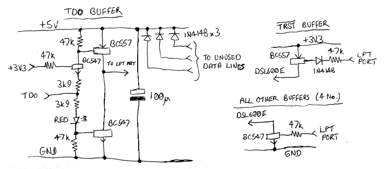
Normally I use a hex inverter chip for buffering parallel port interfaces, but that wasn't possible in this instance. I didn't have any 74HC04s, and a 40106 is shit on 3.3V - on so low a voltage it has an output impedance of somewhere around 2.5k and so is not able to pull any of the JTAG lines low against the 4.7k pullups on the DSL600E PCB. (A lot of printer ports have similarly high impedance and this is another reason to expect a purely passive adaptor not to work.) But on the other hand those same savage pullups mean that a totem pole driver for the inputs is not necessary and a straightforward open collector driver works fine, so I just used a bunch of transistors.
The circuitry looks like this:
And the pinout of the parallel port is as follows. Normal lines are listed with a green background, inverted lines with a red one. Input lines are in bold.
| Pin | Register | Bit | Signal |
|---|---|---|---|
| 1 | Control | ~C0 | ~STROBE |
| 2 | Data | D0 | DATA_0 |
| 3 | Data | D1 | DATA_1 |
| 4 | Data | D2 | DATA_2 |
| 5 | Data | D3 | DATA_3 |
| 6 | Data | D4 | DATA_4 |
| 7 | Data | D5 | DATA_5 |
| 8 | Data | D6 | DATA_6 |
| 9 | Data | D7 | DATA_7 |
| 10 | Status | S6 | ACK |
| 11 | Status | ~S7 | ~BUSY |
| 12 | Status | S5 | PAPER_OUT |
| 13 | Status | S4 | SELECT_IN |
| 14 | Control | ~C1 | ~AUTO_FEED |
| 15 | Status | S3 | ERROR |
| 16 | Control | C2 | INIT |
| 17 | Control | ~C3 | ~SELECT |
| 18-25 | n/a | n/a | GND |
The TDO line, being an output, needs a level shifter and line driver to drive the cable and parallel port. The required +5V supply is derived via diodes from three unused output lines on the parallel port, which should therefore be set high. (It comes out as more like 4.5V, after the diode drops, but that's good enough.) The +3.3V supply comes from the DSL600E. The red LED is not an indicator but a convenient way of dropping 1.8V to make sure the bottom transistor turns off properly and does not significantly overlap in conduction with the upper one. It does glow, but extremely dimly.
The ~TRST line has a 4.7k pulldown, rather than a pullup, so it needs a PNP open-collector driver. The diode protects against reverse-biasing the base-emitter junction, although it probably doesn't matter with only 1.7V possible reverse bias.
The other inputs - 4 in all - have NPN drivers, and reverse bias doesn't come into it.
The obvious question now is, which pins on the LPT port should the lines be connected to? And the answer now is, whichever the fuck you like (as long as the output pins used are the data port ones and not the control port). The openocd documentation contains links to pages describing various different boughten cables, but half of the links don't work any more and most of the ones that do work are shit, so I figured I'd just wire it up however I found most convenient and then hack openocd to accept cable mapping definitions in the configuration file. Of course, when I came to do this, I discovered that the bit of the source code that defines the built-in cable mappings is a far more useful piece of documentation than any of the shitty links in the real documentation, and had I looked at that first I would have had no difficulty at all in wiring the adaptor to correspond with one of the built-in definitions. But by the same token it made the hack pretty straightforward to do, so I decided to carry on as I was; urjtag already allows for user-defined cable mappings (although it has a dog's cunt, see below), and it would be generally useful for openocd to be able to do it as well. And while I was at it I added a parport_cable_list command to print out the various supported cable mappings (note that as with most interface-specific openocd commands, you need to have first defined the appropriate interface (in this case using interface parport) before the command will work.)
The configuration file entry to make use of this facility looks like this:
parport_cable kuzdumm TDO_MASK,TRST_MASK,TMS_MASK,TCK_MASK,TDI_MASK,SRST_MASK,OUTPUT_INVERT,INPUT_INVERT,PORT_INIT,PORT_EXIT,LED_MASK
The eleven parameters are all two-digit hex numbers and must be entered without spaces. Their meanings are most easily described by quoting the relevant section from the openocd source code:
uint8_t TDO_MASK; /* status port bit containing current TDO value */ uint8_t TRST_MASK; /* data port bit for TRST */ uint8_t TMS_MASK; /* data port bit for TMS */ uint8_t TCK_MASK; /* data port bit for TCK */ uint8_t TDI_MASK; /* data port bit for TDI */ uint8_t SRST_MASK; /* data port bit for SRST */ uint8_t OUTPUT_INVERT; /* data port bits that should be inverted */ uint8_t INPUT_INVERT; /* status port bits that should be inverted */ uint8_t PORT_INIT; /* initialize data port with this value */ uint8_t PORT_EXIT; /* de-initialize data port with this value */ uint8_t LED_MASK; /* data port bit for LED */
Note that with the circuitry described above, all lines are inverted. The corresponding bits in OUTPUT_INVERT must therefore all be set. Whether or not a bit needs to be set in INPUT_INVERT corresponding to the TDO line depends whether you wire that line to a non-inverting input pin or an inverting one. (I used a non-inverting one, and so did need to set the appropriate bit.)
An example of the usage is provided by the revised openocd configuration file I used with the home-made adaptor:
interface parport parport_port 0 parport_cable kuzdumm 08,10,04,01,02,08,1f,08,ef,1f,00 adapter_khz 200 reset_config trst_and_srst source /usr/share/openocd/scripts/target/ti-ar7.cfg flash bank 0 cfi 0x90000000 2097152 2 2 $_TARGETNAME
Note the line adapter_khz 200. Experimentation showed this to be an approximate maximum for reliable operation. YMMV. The maximum value for the parameter is 500. But even at 200, it is still ONE FUCK OF A LOT FASTER than the bloody blaster thing on USB.
Of course, urjtag needs its own configuration file ~/.jtag/rc to be edited as well. Now this, which one might suppose to be a simple task, turned into a fucking massive saga because urjtag is a crappy flaky piece of shit. I mentioned earlier that whereas openocd needed to be hacked to support user-defined cable mappings, urjtag already has that facility, so it ought to be a lot easier. In fact it turned out to take a fucking sight longer than writing the hack for openocd, be a lot more difficult, and involve a lot more pissing with the (bloody horrible) source code to try and figure out what the fuck was going on. It also involved a lot more swearing.
urjtag DOG'S CUNT #2
The only documentation of the user-defined cable mapping facility, as far as I can see, is that obtained from within urjtag itself, by issuing the command cable wiggler help. It says this:
Usage: cable wiggler parallel PORTADDR [TDO,TRST,TDI,TCK,TMS,SRESET] or: cable wiggler ppdev PPDEV [TDO,TRST,TDI,TCK,TMS,SRESET] PORTADDR parallel port address (e.g. 0x378) PPDEV ppdev device (e.g. /dev/parport0) TDO, ... parallel port bit number, prepend '#' for inversion default is '7,4,3,2,1,#0'
Which looks pretty straightforward, and translating the openocd config command according to that information indicates that the urjtag cable wiggler ppdev /dev/parport0 #3,#4,#1,#0,#2,#3 ought to do the trick.
It doesn't. It doesn't complain about it, but it doesn't fucking work, and seemingly nothing you do to it has any result other than to produce bizarre error messages which make no sense.
To cut short a very long story involving far too much of trying to trace urjtag's fucked-up command parsing through its tangled and hideous source code, the explanation turned out to be remarkably simple:
The built-in help output quoted above is FUCKING WRONG. It fails to mention that you need the key bitmap, and an equals sign, before the list of pins. The correct syntax is:
Usage: cable wiggler parallel PORTADDR [bitmap=TDO,TRST,TDI,TCK,TMS,SRESET] or: cable wiggler ppdev PPDEV [bitmap=TDO,TRST,TDI,TCK,TMS,SRESET]
Why the pissing fuck. I mean, chicken's tits. It took me bleeding hours to fucking find that out. Still, at least now I have worked it out and posted it on the internet so hopefully nobody else has to.
It is also necessary, as with openocd, to configure the adaptor clock frequency. Again, straightforwardly translating the openocd config command according to the urjtag documentation would lead you to believe that frequency 200000 would do the trick. And, again, it fucking doesn't. I ended up having to use a value of 160000 to make it work; what the actual frequency is fuck only knows.
Did I mention that urjtag is a crappy flaky piece of shit? THIS, for fuck's sake, is the code that defines the period of the clock waveform:
void urj_tap_cable_wait (urj_cable_t *cable) { int i; volatile int j; j = 0; for (i = 0; i < cable->delay; ++i) j = i; /* Avoid gcc set-but-unused warnings */ cable->delay = j + 1; }
A FUCKING FOR LOOP. On a MULTITASKING OPERATING SYSTEM. You have NO FUCKING IDEA how many times that loop is going to execute in any given time interval. The fucking program even demonstrates this to you. The delay value is set during the execution of the frequency command, comparing the effect of different values against a system timer and adjusting the value iteratively to home in on the right result. It prints out the results of what it's trying as it goes along, and you can see it printing out stupid values. You can see the algorithm getting flustered as it tries to deal with results that don't make sense because the delay varies arbitrarily according to how much of the period it's measuring over the process was actually executing for. And, more obviously, you can see it getting a different fucking result every time you run it.
And this is doing it on a machine with 8 cores so that a process that wants to hog CPU in one thread can usually get a core mostly to itself to do it on. Fuck only knows what it would be like on a single core, or even two. I'd probably have to kill -SIGSTOP the fucking browser while urjtag was running otherwise every time some javascript went off on a timer urjtag would shit itself. Remember when you used to have to shut everything down while you wrote a CD for fear of buffer underruns? Anyway, I do think it is worth saying this:
Do not use urjtag over the parallel port to write to flash memory. Use a blaster thing instead. Even though the parallel port is much faster than a blaster thing, writing still takes bleeding ages, and there is always the risk of the clock going haywire and buggering it up. Better to take a long time over doing it once than to do it more quickly and find it didn't work and have to do it again (and again, and again, swearing more with each iteration). Note that even if you configure a slow clock speed with the parallel port, it is still vulnerable to the process scheduler screwing it up. With the blaster thing the speed is set by the limitations of the hardware so it is less liable to random variation.
Anyway, after trogging through all that shite, I ended up with the following for ~/.jtag/rc:
cable wiggler ppdev /dev/parport0 bitmap=#3,#4,#1,#0,#2,#3 frequency 160000
Back to AR7 Index
Back to Pigeon's Nest
Be kind to pigeons
![]()