Wheel Brakes
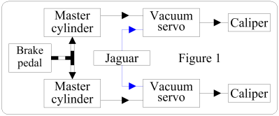
This is the simplest hydraulic circuit, presumably the same as on normal cars. Two master cylinders are shown in the Genome, so I assume that there are two separate circuits, one for each wheel. For an explanation of how brakes work, see elsewhere in this website under "Howard's Stuff". A simple block diagram suffices.
A Note On Drawings
The drawing on the right comprises blocks, one for each function. This is the best drawing to enable a user of a machine to see what's happening. Designers of electrical, electronic & fluidic circuits use circuit diagrams which use symbols for every component. These diagrams are a very convenient form for designing & fault-finding. Familiarity with the symbols enables one to work out exactly how the machine works, hence their use in fault-finding. On the website Andy Green shows a "typographical map" of the hydraulic circuit which appears to be neither a block diagram nor a circuit diagram. The circuits shown below are in circuit diagram form.
A Note On The Circuit Diagrams
It is not possible to work out how the hydraulic circuits work from Andy's drawings, & the Genome is incomplete ("...every nut & bolt..."?) so the diagrams are of circuits to my design. They are certainly not the Bloodhound circuits, but they are correct in that they perform the necessary functions, & won't differ very much from the real ones.
An Explanation of the Symbols
An accumulator is an enclosure split into two chambers by a piston. The chamber next to the hydraulic pipe is connected to that pipe & is full of liquid. The other chamber is full of inert gas, usually nitrogen, under pressure. If the hydraulic supply fails, the accumulator can supply pressurised liquid to the service sufficiently, at least, to get that service to a safe state. Fluctuations can occur in the supply due to the operation of devices & the accumulator can damp these.
Actuators, sometimes called jacks, are cylinders with pistons enclosed. Ports in the cylinders are symbolised by triangles. Feed liquid into one port & the piston is pushed one way, & vice versa. Alternatively, the piston can be driven one way by liquid, & returned by a spring.
Pressure regulators control the pressure. The lefthand one is preset to fixed pressure, & the righthand one receives a variable voltage to vary the pressure. They work by diverting excess liquid back to the tank.
Transducers are devices which detect the value of the parameter being measured & convert it into a convenient form which is given as an output. P means that pressure is being measured, & T, temperature.
Imagine a length of material held by one end in a vice. Pressing on the free end will deflect that end, bending the bar. Even if the deflection is so minute that a human cannot detect it, devices called strain gauges can measure it. The deflection is proportional to the deflecting force, or load, so strain gauges are load transducers, LTd.
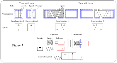
The top left of Figure 3, the Valve with 2 ports, shows the cross-section of a cylinder, the body, with a piston, the spool, inside. There are holes, ports, in the body wall for the connection of the hydraulic pipes, & there are holes, passages, in the spool. The spool is at one end of the body, & the ports are blocked, so nothing happens. The symbol is shown below. Then there is a picture of the spool at the other end of the body & the ports are connected by the passage, so liquid can flow throught the valve.
The Valve with 5 ports works exactly the same way, the spool shuttling between the ends of the body. The symbols show closed ports by T, & connected ports with a line joining them. The arrow heads show the direction of flow.
The spool can be moved by a wide variety of devices, called operators. Two, a spring & a solenoid, & their symbols are shown. The construction shows these built into a valve with two ports, forming an electrically-controlled Open/Close valve. This is symbolised by adding all the relevant symbols. The operators are put next to the spool position which they cause; if the solenoid is energised it will move the spool to the "valve open" position, 2. In a circuit diagram the pipes are shown by lines to the ports in the normally de-energised part of the symbol.
The Hydraulic Circuit
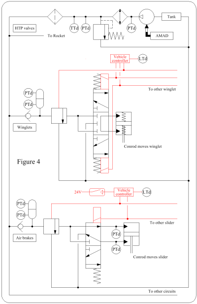
The circuit diagram has been composed from Andy's drawing as much as possible, & is shown in Figure 4. Note that the circuits for the left & right devices are the same, so only one of each is shown.
Starting with the supply. The AMAD mechanically drives the pump, which draws liquid from the tank & drives it through a cooler (like a car radiator; not shown in Andy's drawing). A regulator controls the pressure to the maximum required by the circuit, & then the liquid is filtered.
The Winglet Circuit
The first item, a one-way valve, ensures that the accumulator can operate the circuit if hydraulic pressure is lost. The 5-port valve is deenergised, the computer (Vehicle Controller) not energising the solenoids, & its springs moving the spool to its central position. In this position it connects both ends of the actuator, equalising the pressures. This means that the springs in the actuator can centralise the piston, driving the winglet to its aerodynamically neutral position.
Load transducers mounted somewhere in the suspension measure the loads on the wheels. If Bloodhound starts to pitch, these loads will change. The computer will then move the main valve spool up or down by energising the appropriate solenoid. When the spool is in one of these positions liquid flows through one passage to one end of the actuator, & liquid from the other end of the actuator flows through the other passage back to the tank. The piston is driven in the appropriate direction. If the rate of change of pitch is high, the computer will operate the regulator to supply a high pressure, so the response of the piston is fast.
Hopefully, the winglets will not be used (one less thing to go wrong, & consider what would happen if the circuit failed in such a fashion that the winglets jerked to their fully nose-up position). During test runs, telemetry will enable the engineers to monitor the winglet actions & see if they are needed. If they are needed, this monitoring will also enable them to fine tune the rate of the winglet's response to pitch changes.
The Airbrake Circuit
When hydraulic pressure is first applied the liquid flows through the one-way valve, the regulator & the main valve to drive the actuator piston & deploy the brake. Andy then presses the button & the pulse tells the computer to energise the solenoid of the main valve, so the actuator piston moves to retract the brake.
When Andy is slowing at 800mph he presses the button & this time the response of the computer is to deploy the brakes by denergising the solenoid.
As the brakes are pushed out the drag force increases. If they were pushed fully out at this speed this force would exceed what the chassis can withstand. So the computer limits the pressure supplied by the regulator, letting it rise until the force is at the safe limit of the chassis's strength.
Load transducers mounted somewhere in the airbrake mechanism measure the drag force, & it is this measurement that enables the computer to control the regulator.
As Bloodhound slows, the drag decreases & the regulator pressure increases, pushing out the brakes.
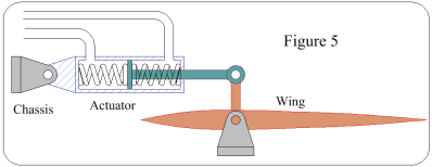
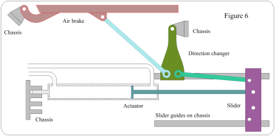
Figures 5 & 6 show the mechanical bits, but they are redundant because they can be seen in the Genome. This particularly applies to Figure 6, because there is an animation on the website.
