The sketches are not to scale but all parts can be identified in the Genome.
The Front Suspension
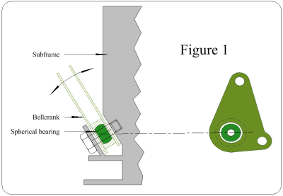
Figure 1 shows the Bellcrank mounted in the Subframe. As explained below, the Bellcrank must move as indicated by the curved arrow. This means, I deduce, that there is a spherical bearing between the Bellcrank & the Subframe; it is shown here. The deduction is borne out by the showing of the housing of the bearing, in the Genome.
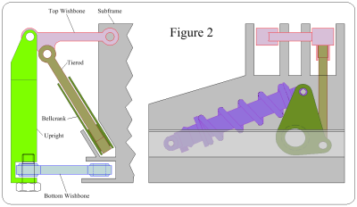
Figure 2 shows the suspension parts with the wheel at midpount in its vertical travel; the Genome does the same. The Upright & Bottom Wishbone are omitted in the side elevation.
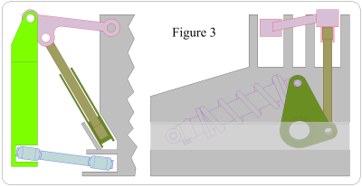
Figure 3 shows the suspension at full compression.
Looking at the rear elevation, the limit is decided by the spherical bearings in the Bottom Wishbone. As the Top Wishbone moves round its Subframe mounting point, the top mounting point of the Pullrod moves round the same point.
So the Pullrod is turned round an arc centred on its bottom mounting point; this movement twists the Bellcrank which turns round its spherical bearing.
The Pullrod is also pulled vertically. This turns the Bellcrank, again round its spherical bearing.
Now looking at the side elevation, which omits the Bottom Wishbone & the Upright, the Bellcrank has been moved round a longitudinal axis (by the Pullrod), moving the Suspension Unit's top mounting point. This is catered for by the Suspension Unit having spherical bearings at both ends. The Pullrod's vertical movement has turned the Bellcrank as shown.
The Bellcrank has now compressed the Suspension Unit. The Suspension Unit has internal stops to limit the suspension travel.
Once over the bump, the Suspension Unit pushes the Bellcrank back, & the Pullrod pulls the wheel down.
Comparing Figures 2 & 3 notice that the Upright (& the Wheel) moves vertically up & down. Any
turning or movement in or out can be tolerated in a saloon car, but is undesirable in Bloodhound.
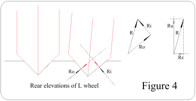
Figure 4 shows the wheel turned. The weight borne by the wheel presses on the desert through two components shown by the red arrows, & the desert's reactions, R1 & R2, are shown by the black arrows. Ri & Ro are added as shown in the triangle, giving the resultant R. In the rectangle R is resolved into vertical & sideways components, Ru & Rs. Rs turns the Wheel using its castor action. "I don't want that", said the Wingco. The rolling resistance (the drag of the desert on the wheel) increases, increasing the stresses in the involved parts & slows the car. "I don't want that", chorused Mark & Richard.
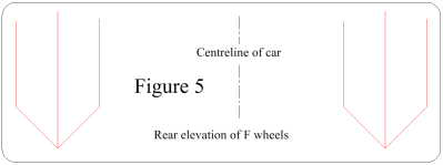
Figure 5 shows movement in or out. More room inside the car will be needed, & this will increase the car's frontal area. "I don't want that", said Ron.
The Rear Suspension
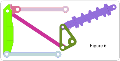
This is simpler than the front suspension, because the Bellcrank has to move round only one axis. Otherwise it is the same. As can be seen in Figure 6, when the wheel moves up, the Pullrod pulls the Bellcrank round, & this compresses the Suspension Unit.
The long rods running forwards & inwards from the Upright do not affect the suspension; they stop the wheels being dragged off the car.
