
Figure 1
How does the missile know where it is at all times? It knows this because it knows where it isn't. By subtracting where it is from where it isn't (or where it isn't from where it is, depending on which is greater), it obtains a difference or deviation. The internal guidance machine uses deviations to generate corrective commands to drive the missile from a position where it is to a position where it isn't.
In the event that the position where it is now is not the same as the position where it originally wasn't, the machine will acquire a variation (variations are caused by external factors, and the discussion of these factors is not considered to be within the scope of these notes), the variation being the difference between where the missile is and where the missile wasn't. If the variation is considered to be a significant factor, it too may be corrected by the internal guidance machine.
Moreover, the missile must now know where it was also. The thought process of the missile is as follows: because a variation has modified some of the information which the missile has obtained, it is not sure where it is. However, it is sure where it isn't and knows where it was. It now subtracts where it should be from where it wasn't (or vice versa) and by differentiating this from the algebraic difference between where it shouldn't be and where it was, it is able to obtain the difference between its deviation and its variation, this difference being called error.
This company also produces an extremely accurate command-guidance machine, but this type of guidance does not lend itself to simplification of theory.
This was written by a designer of inertial guidance machines, & is correct.
**********************************************************************
A navigational aid which continually measures the acceleration of a vehicle, & from this information computes velocity &, if required, the distance travelled from a known position. To measure distance travelled through space, aircraft systems normally use two accelerometers orthogonally mounted, & missile systems use three accelerometers orthogonally mounted. The axes of the accelerometers are kept aligned with the local N-S, y, E-W, x, & Up-Down, z, axes.
The platform must be stabilised in space & be capable of controlled movement as required. This alignment is made continuously, by turning, or precessing, the accelerometer frame at certain computed rates. For correct operation, the accelerometer platform must be completely independent of the vehicle pitch, roll & yaw motion. If the platform is mounted in gimbals, & gyros used to detect movement of the platform from its datum position, the gyros' o/ps can be employed to eliminate errors from the platform alignment.
Because of the problems of component design, which are also extremely expensive due to the accuracy required, the majority of inertial machines are monitored by an additional navigational aid to obtain better accuracy than could be obtained by using either aid alone. The types are:
The Doppler/Inertia machine: A doppler radar can provide accurate groundspeed & drift measurements, but an accurate heading source is needed. This is provided by the Inertial Navigation Machine, INM, & a technique known as Fixed Monitored Azimuth, FMA, is used to correct the machine & to obtain correct fixes.
The Stellar/Inertial machine: The inertial machine is in this instance monitored by an automatic star tracker; useful for long range navigation but is a high altitude machine, because it will not work if the stars are obscured by cloud.
Doppler/Stellar/Inertia machine: More complicated but provides better accuracy than either of the two previous machines in a shorter time. It is not affected by cloud obscuring the stars.
Acceleration is defined as the rate of change of velocity with time. It can be found when the rate of change of velocity is constant, by the formula: a = v/t.
In this instance acceleration would also be constant; but it is unusual to find constant accelerations &, practically, acceleration varies all the time over a distance. To find the total acceleration all the small changes must be added together over a given period of acceleration. This cannot be done by using the simple formula above, but it can be done by integration. The process of integration can be carried out practically by mechanical or electronic equipment.
Transposing the above formula, v = a.t. If velocity is known the
distance travelled is: s = v.t. Thus if acceleration is integrated with time
once, velocity is obtained; if integrated with time again, distance travelled
is the result.
Velocity = ∫a dt
Distance travelled, s, = ∫∫a dt.
A practical example of velocity integration is a car milometer, which gives information of distance travelled.
If acceleration is measured in terms of a dc o/p & fed to a motor driving a shaft, the total angular rotation would be proportional to velocity. If velocity were then measured in terms of a dc o/p & fed to a similar motor, the total angular rotation would be proportional to distance travelled.
Referring to Figure 1, the mass will be displaced left if the acceleration is to the right. The force required to displace the mass is provided by the acceleration & that force will be balanced by the spring causing the mass to stop moving. Thus the force produced by the acceleration & the displacement of the pointer from zero, is proportional to the acceleration.

Two accelerometers mounted as shown in Figure 2 would measure accelerations in the N/S & E/W axes individually, whilst acceleration NE for example, would have its component parts of N & E accelerations measured by the appropriate accelerometers. Two counters could be provided which would give distance travelled from a starting point or alternatively, longitude & latitude, if set up to the starting longitude & latitude.

Platform Tilt: Consider Figure 3. The platform tilt has caused gravity to act upon the mass to move it, which is the same movement produced by the acceleration in Figure 1. The platform is not accelerating however & an error is present.

Platform Misalignment: If the platform were misaligned, as in Figure 4, then what should be recorded as acceleration along the N/S axis only, is, due to the misalignment, recorded as acceleration in the N/S & E/W axes, which will again cause an error.
As the platform can tilt in any direction & also yaw, the need for a stabilized platform is established.
These components must be able to measure a wide range of acceleration. It is difficult to obtain a wide range, high sensitivity, quick response & a dead beat system.

The following are examples of the simple principles of some practical accelerometers:
a) Force Feed Back
In Figure 5, when the accelerometer containing the permanent magnet
moves, the centre plate of the capacitor moves with it, thus the capacity on
one side increases & on the other side decreases.
The resultant current flow between points A & B has a phasing dependant on the direction of vane movement & an amplitude which depends on the amount of vane movement.
This signal is then passed to a discriminator, the size & polarity of the o/p being determined by the phasing & amplitude of the i/p.
After amplification the o/p is fed to the restoring coil &, depending on the polarity, will flow from E to F or vice-versa. The field so produced about the coil will oppose the movement of the permanent magnet contained in the accelerometer, giving a dead beat system.
As the current flow through the coil produces a restoring force which is equal & opposite to the displacing force, & proportional to the acceleration, the current value is a measure of the acceleration, whilst it's polarity is an indication of the direction of the acceleration.
b) Resonant Devices
If a tuning fork is made
to vibrate, its frequency will change with acceleration. Thus if vibrating at
resonant frequency, the integral of acceleration can be obtained by counting
electronically the number of cycles lost or gained due to acceleration over an
interval of time.
c) The Integrating Gyro-Accelerometer
Refer to Principles of Gyroscopes.

There are two main types:
a) Electromechanical Integrators
Referring to Figure 6, if acceleration o/p
voltage is fed to the motor via the amplifier the motor & tachogenerator
will start to rotate, the tachogen trying to balance the o/ps. Any difference
in the o/ps causes the motor to speed up or slow down. The rate of rotation
of the motor is directly proportional to the acceleration voltage & thus,
as with the integrating gyro-accelerometer, the angle through which the motor
shaft rotates is the integral of acceleration, ie velocity, which can be
indicated on instruments or used to drive a potentiometer to provide an o/p for
a second stage of integration.
b) Electronic Integration
Which is done in the computer.

The need for a stabilized platform was given. This is achieved by using dislacement gyros. The gyroscopes used are precision types & have less than 0.1°/h random wander under laboratory conditions; such accuracy is required in all components of an inertial system.
Referring to Figure 7, the platform is supported on three gimbals. Any movement of the gimbals is detected by the appropriate integrating gyro which actuates a signal generator, the o/p of which operates a servo motor, driving the gimbal & platform back into alignment with the gyro. If displacement gyroscopes are used, only two are required.
This is satisfactory for any position where the aircraft axes are aligned with the platform axes. However, if the platform is aligned with True North & the aircraft is flying at 45°True, then a movement of the platform about its roll axis, is a movement in roll & pitch in relationship to the aircraft axes, & the pitch & roll servos must be actuated to stabilize the platform.
Only the roll gyro is providing a signal & this must be divided between the two servo-motors in the correct proportions to obtain operation of the roll & pitch servos on the gimbals to bring the platform back to its original position.

Misalignment of this nature can occur on any aircraft heading & so all signals from the roll & pitch axes gyros are passed through the resolver before being fed to their respective servos.
The platform is now stabilized with respect to space.
Because the inertial system is to be used within the confines of the Earth it must be stabilized with respect to the Earth & its axes must remain aligned with the local N/S, y axis, the local E/W, x axis & the local vertical, z axis, as shown in Figure 8.
If the platform is stabilized relative to space & is stationary relative to the Earth, then as the Earth rotates the platform would tilt relative to the Earth, & the accelerometer in that line of tilt would register acceleration which is unwanted, thus causing an error.

To correct for this error the platform must be turned relative to a fixed point in space, in the same direction & at the same angular velocity as the Earth, ie 15°/h, about an axis parallel to the Polar axis, see Figure 9, & also if the platform is to remain aligned with the local x, y, z axes it must move with the Earth & in the same direction as the Earth. Thus movement must take place about the y axis to maintain the local vertical & about the z axis to maintain heading.
The apparent platform tilt is detected by the gyroscopes & a signal, obtained either as a direct feedback after the first stage of integration or from a mixture of Doppler groundspeed signals & inertial velocity feedback, is applied to torque motors situated on the inner axes of the gyroscopes, causing precession. An error signal is thus provided, which, fed to the appropriate servo, causes the platform to move about that axis.

When all the precession signals are applied to the platform it will remain aligned with local x, y, z axes if the vehicle does not move relative to the Earth.
When the vehicle moves relative to the Earth further factors must be considered. In Figure 10 an aircraft is shown at A flying horizontal to the Earth's surface towards B, with the platform maintaining its position. When the aircraft arrives at B the platform has tilted back from the direction of flight because it has maintained its position relative to space. The plaform must therefore be rotated about the x axis at a rate equal to the aircraft's angular velocity about the Earth's curvature, ie NS groundspeed/Earth's radius.
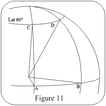
In Figure 11 it can be seen that a vehicle travelling from A to B on the equator will travel a greater distance than from C to D at 60°Lat, but more important is the radius of the circle through which the vehicle is travelling, for this is going to give a variation in angular velocity, ie the angular velocity at the equator is greater than at 60°Lat. For example, at the equator the angular velocity = 1000mph, but is only ~700mph at London.
Thus to maintain the platform alignment with the local vertical & its heading irrespective of its position over the Earth's surface, corrections must be made & applied to precess the platform about the y & z axes at a rate decided by the aircraft's angular velocity about the Earth's curvature, ie E/W groundspeed/Earth's radius.
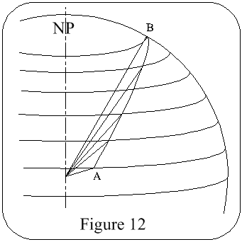
Now consider Figure 12, the vehicle is travelling from A to B; it can be seen at once that corrections proportional to the N/S & E/W groundspeeds/Earth's Radius must be applied continually.
These signals are obtained from the N/S & E/W accelerometer o/ps after the first stage of integration & after computation are applied to the appropriate gyros as straight signals or the resultants of signals. The platform should now remain aligned with the local x, y, z axes of the Earth.
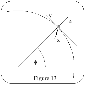
Earth Rate Error: Referring to
Figure 13, consider the vehicle stationary, being carried around by the earth
at Ω°/s. Maximum o/p of the z axis at the poles. Maximum o/p of the y axis
at the equator. No o/p of the x axis at the poles or equator. With the
vehicle at φ°latitude:
y = Ωcosφ
z = Ωsinφ
Vehicle Rate:
Measurement N - S
Angular velocity = Linear velocity / Radius of rotation
Linear velocity, V, is the vehicle's ground speed
The platform will turn @ a rate of V/R rad/h about the X axis.
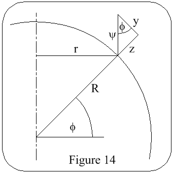
Measurement E - W; referring to Figure 14
Vehicle velocity = U
Angular velocity = Ψ
r = Rcosφ
Ψ = U/r = U / Rcosφ
y = Ψcosφ = U/R
z = Ψsinφ = Utanφ / R
Precession Terms
| Correction Term | x axis | y axis | z axis |
| Earth Rate | - | Ωcosφ | Ωsinφ |
| Vehicle rate | V/R | U/R | Utanφ / R |
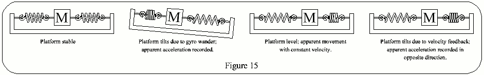
Referring to Figure 15, if gyro drift, table misalignment with the x, y, z axes, or computer errors occur, a false signal will be applied to the appropriate servo & the table will tilt. The accelerometer at right angles to the axis of the tilt will record an apparent acceleration, which will be integrated to give a velocity output & a distance error. Velocity feedback will now occur & the table will be driven back horizontal with the earth, the accelerometer signal being removed. However the apparent situation is now that the platform is moving with zero acceleration but at constant velocity. The velocity feedback signal is therefore still applied causing the table to be driven to the opposite tilt and the whole action becomes repetitive. The platform will oscillate in a similar manner to a simple pendulum.
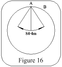
A simple pendulum in a stationary vehicle, or a vehicle moving at constant speed, will always indicate the true vertical, but not if the vehicle is accelerating. The only pendulum which would be unaffected by acceleration would be one having a length equal to the radius of the earth, ie, a Schuler pendulum, Figure 16.
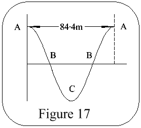
If the pivot point A is accelerated towards B there is no effect on the pendulum bob as it remains hanging towards the earth's centre. If the pendulum was oscillating, the period of oscillation would be 84.4m, & at the centre of every swing, every 42.2m, a reference to the true vertical would be obtained; see Figure 17.
Acceleration of the pivot point will not affect the period of oscillation, nor will the amplitude of the swing. Thus if the platform is made to oscillate with an 84.4m period by adjustment of the velocity feedback it will be unaffected by the vehicle acceleration & every 42.2m a true vertical will be indicated.
Such a system is usually employed for platform monitoring in missiles of inter-continental class or in penetration aircraft where Doppler monitoring cannot be used due to its being detected by opposing forces. Where the "stand-off" principle is used or the missile is carried by submarine to the release point, the time of flight is relatively small & Doppler or some similar monitoring can be used up to the release point after which it is guided on the last stage of its journey by the pure INM. For all peaceful aircraft navigation Doppler monitoring is used. In deep space Schuler Tuning would be unnecessary.

Velocity can change either in magnitude or direction, thus if a vehicle accelerates in a straight line the magnitude is changing, but if it moves in a curve at constant speed the direction is changing, & acceleration is present toward the centre of the curve, ie centripetal acceleration.
Referring to Figure 18, it can be seen that for a vehicle travelling in an E/W path the centripetal acceleration will affect the outputs of the x, y, z accelerometers, if not in line with one of these axes, in proportionate amounts to the o/ps of those accelerometers, being maximum at the equator & minimum at the poles. Similar errors will occur if the vehicle travels on a N/S path.
These are unwanted accelerations & must be corrected by signals from the computer.

This effect is divided into vertical & horizontal components.
Vertical Component: Referring to Figure 19, the constant easterly deflection in either hemisphere acting on a vehicle is due to the earth's rotation. The amount of deflection is governed by altitude & latitude.

Horizontal Component: Referring to Figure 20, the resultant of the vehicle's coriolis force & gravity effect, which will vary in amount with latitude change, being smallest at the equator & becoming greater towards the poles, causes a deflection to the right of the vehicle in the Northern hemisphere & to the left in the Southern hemisphere.

Total Effect Of Coriolis: Referring to Figure 21, the vehicle must travel in a curved path from A to B due to the movement of the arrival point from B to B4 caused by the earth's rotation; at the same time, due to the curved path, the x, y, z axes move relative to space & produce unwanted errors. Correcting signals, which vary with latitude, altitude & vehicle speed are supplied from the computer & fed to the relevant accelerometers.
Howard's Stuff Index
Back to Pigeon's Nest
Be kind to pigeons
![]()