

| Engines | 2 Napier Eland NEI3s |
| Engine output | 2.24MW each |
| Wingspan | 14.17m |
| Length | 17.88m |
| Height | 6.76m |
| Maximum speed | 307km/h |
| Rotor diameter | 27.43m |
| Maximum range | 734km |
| All-up weight | 14,968kg |
| Accomodation | 40 passengers |
The Rotodyne was a relatively difficult craft to fly. The only details available are in a Flight magazine article (Rotodyne, 1957), which is the basis of this one. Refer to the Flight article (PDF) for more details (for tip-jets see Wittgenstein; yes, that one). Text in red indicates help for the pilot.
In the Rotodyne the loading on the rotor was reduced by sharing the lift at cruising speed with the wing & using propellers instead of the rotor for forward propulsion. At normal forward flight the wings contributed 60% of the total lift; the remaining 40% was generated by the rotor blades.
While hovering the Rotodyne was a helicopter. While in forward flight it was an autogyro.
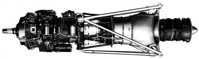
For propulsion two Napier Elands operated as dual-purpose powerplants - acting either as normal turboprops or as compressors. They were virtually normal Elands up to the rear of the turbine casing. The jet pipes were bifurcated, exhausting through the sides of the nacelles ahead of the rear firewall. The turbine shaft was extended through the wall & drove a hydraulic clutch which drove a nine-stage axial compressor. In autogyro mode they provided 100% thrust for forward flight. In helicopter mode they used up to 80% of engine power to supply air to jet engines on the ends of the rotor blades, & 20% for yaw control. The Elands worked at constant speed, thrust being varied by propeller pitch.
For starting the clutches were engaged & the propellers set to neutral pitch. When the rotor rpm was sufficient, a normal helicopter start was made. The Rotodyne took off (& landed) as a helicopter, using cyclic pitch for roll & pitch control. Yaw control was achieved through differential pitch applied to the propellers.
Transition into forward flight started by application of forward cyclic & collective pitch to achieve a steady climb at 60-80kt. When the Rotodyne had gained sufficient altitude differential propellor pitch control was reduced until at 80kt the rudders could exert their full control. Controlled flight to the transition speed of 110kt was maintainable with the rotor. Transition was achieved by increasing propeller pitch & reducing power on the rotor until the tip-jets were at idling power & the propellers providing practically all the forward thrust. At this stage fuel to the rotor was switched off & the compressors disengaged. The rotor speed was then allowed to settle in autorotation with approximately 2° of collective pitch. With the rotor off-loaded in this fashion forward speeds up to 160kt could be easily achieved. It should be noted that at the time this was a very high speed for any rotorcraft.
Control in the autogyro regime was maintained through a combination of cyclic pitch on the rotor & conventional aerodynamic control surfaces.
Transition back into helicopter flight was essentially a reversal of the procedure: reduce speed to 110kt, engage compressors, switch on fuel & ignition. Below 80kt, progressively more differential propeller-pitch control was introduced to replace the rudder moment, which gradually fell off with speed although the rudders retained full movement all the way. The differential propeller pitch change was controlled by a mechanical linkage from the clutch control. Precise adjustment of this mechanism was obviously a matter for trial and error. It was, however, of the following order: the differential pitch-change starts to operate when the propeller blade angle is reduced to 40° & its range increases to a maximum of about 5° positive, 5° negative, about the zero-thrust setting. Usually helicopter flight was re-established within 4-5 seconds.
The control of the rotor was still available in the event of both engines stopping, because it drove its own emergency hydraulic supply.
The Rotodyne could land on an area as big as two tennis courts.
In its original form the controls were direct roll & fore-&-aft through the cyclic controls, with a trim elevator used to select aircraft pitch in cruising flight, & with yaw control by differential propeller-pitch at low speeds or when hovering, & by rudders at higher cruise speeds; as forward speed increased, the available differential was reduced.
Fairly early in the test programme it was found that the fore-&-aft attitude control, using the separate functions of fore/aft cyclic & elevator trim, produced some difficulties. The solution was to link the elevator to the fore/aft cyclic control for both slow & high-speed flight & to disconnect the cyclic control when cruising. Similarly for ailerons, the operation of which was linked directly to the lateral cyclic control of the rotor.

For transition from autogyro to helicopter, operation of the clutch control energises actuator A. This moves the lower lever B through the ineffective sector of the track in cam C, & the upper lever D to move the slider E carrying the pivot F which operates the pitch-control rods G. This must set the propeller pitch.
Further movement of the actuator, out of cruise condition, moves B to the effective track of C. The resulting displacement of C & the attached link moves slider H. Roller I is moved off the centre line of the rudder movement input shaft J. Rudder movement then swings I & H about pivot aa, moving G differentially. The more B moves along the effective sector, the more I is moved off the centre line of J, & the more differential pitch is increased.
The swinging of H turns shaft K, which (via butting stops L) imparts a unidirectional movement to M, limiting the compressor output.
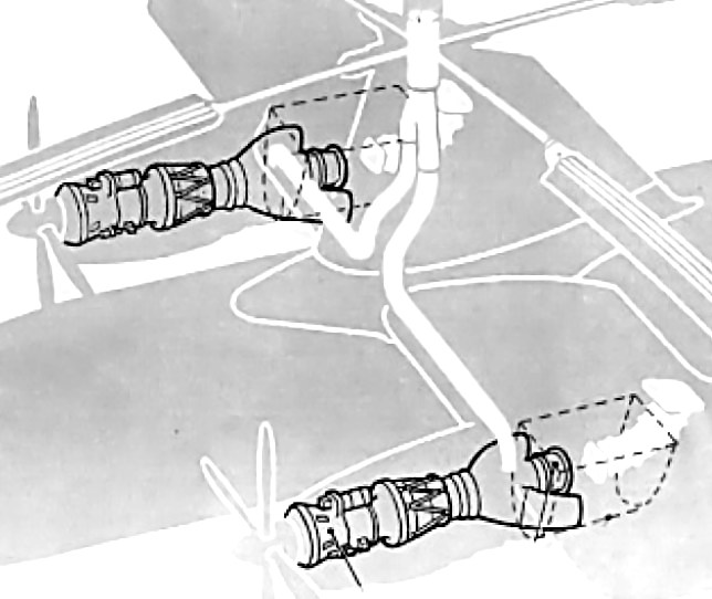
The compressors drew their air through a special intake on top of the wings directly over the engine nacelles, & a few centimetres from the trailing edge. The air was sucked through plenum chambers & into the compressors.
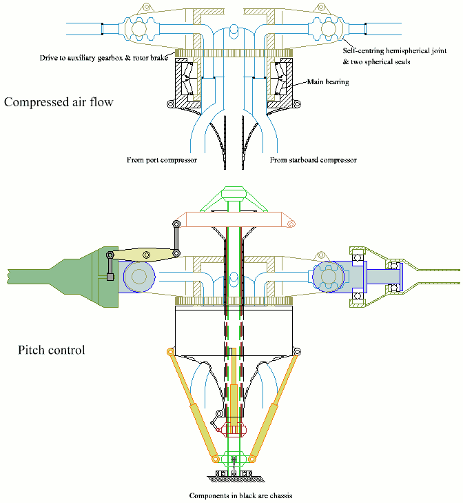
The compressed air was delivered upward, to the leading edges & thence to the main rotor pylon. Here there was the problem of maintaining separate delivery into the rotating head. To achieve this a light alloy casting accepted the two air flows in its "legs" & delivered them through concentric annuli which fed into a fabricated concentric annular duct mounted in the rotating rotor-hub which ingeniously delivered the air from each duct to opposing pairs of blades. Air from the port auxiliary compressor entered the inner duct of the light-alloy trouser casting & the starboard compressor supplied the annular duct around it. The rotating joint between the casting & the fabricated duct was sealed by a graphite-impregnated sintered bronze ring. Dividing the two flows was a labyrinth seal.
With the help of cascades to turn the flows & careful matching of cross-sectional areas the duct losses were kept low. Up the centre of the assembly was the airtight tube within which the concentric control tubes operate; & at the centre of everything was the conduit for fuel pipes, ignition leads & light-up telltale leads to the fuel distributor manifold & respective sliprings.
The sketch indicates some of the sealing problems involved in leading pressurized air at 250°C through flexing ducts. Note also the spar-root taper roller bearings.

The following is what the Flight article says. Even with the associated sketch I do not understand how the pitch control worked.
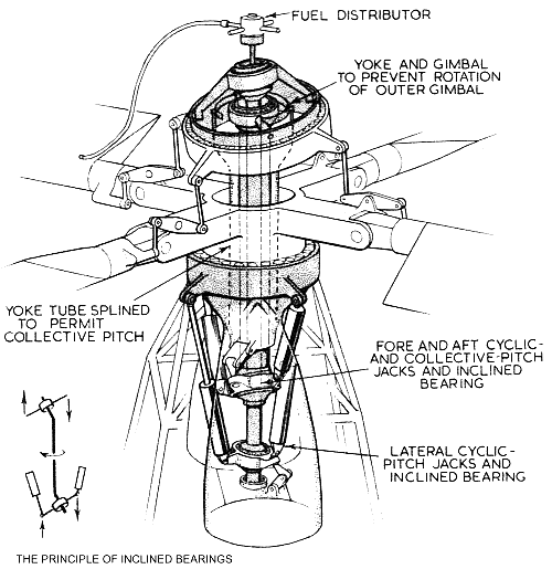
The basic problem in the rotor head was how to get the pitch-change controls round the obstruction of the air ducting. It was solved by mounting the swashplate on top of the rotating head.
The two pairs of control jacks rocked the lower pair of inclined bearings to imparted a rotary motion to the vertical concentric slide/torque tubes & a corresponding rocking of the upper set of inclined bearings, thus tilting the spider.
Collective pitch is obtained by both upper jacks moving in the same sense. The inner tube is splined to allow this vertical movement of outer tube & spider.
The swash plate & actuating linkages, through which cyclic & collective pitch was applied to the blades, were situated above the rotor head, with the operating jacks anchored below the main bearing housing, the action being transmitted by concentric slide/torque tubes.
The two pairs of control jacks ... act on sliding collars mounted on hemispherical bosses on the actuating tubes. The upper collar rotates the outer of the two control tubes to displace, through its canted head, the fore & aft cyclic-pitch linkage, while the lower one similarly operates the lateral cyclic-pitch linkage through the inner tube. The two fore-&-aft jacks operate together to raise & lower the swash plate (which has a driving link to one rotor-blade stub arm only) to give collective pitch change. A splined extension at the foot of the operating tube allows vertical displacement for collective pitch control without affecting the lateral cyclic-pitch jacks.
The things which puzzle me most are the splines & the collective control. To spline the yoke & control tubes would increase stiffness, but the splines would have to be horizontal to enable the rotary motion of the control tubes. The collective control would work if both pairs of jacks were operated normally, but together. Also, I have no idea how the cyclic pitch controls were connected to the elevator trim & ailerons. I'll be grateful for any light which can be shone on these problems.
The sketches below show
how things might work; email address:


Howard's Stuff Index
Back to Pigeon's Nest
Be kind to pigeons
![]()