This design is distributed under the Open Hardware General Public Licence.
Copyright (C) 2006 Pigeon
General description
This is a simple optical trigger arrangement to serve the same function as the mechanical contact breaker on six-volt MZ motorcycles. It can be adapted for other vehicles, including those with more than one cylinder and those with twelve-volt electrical systems. The mechanical contact breaker can be retained to provide a backup in case the electronics fail.
A disc, opaque except for a small sector, is mounted on the same axis as the existing points cam. The small transparent sector is detected by a slotted optical switch and the signal is amplified to provide an electrical equivalent to the mechanical contact breaker.
It is purely a non-wearing replacement for the points and doesn't have any ignition advance function; it is a maintenance convenience and shouldn't make any difference to the running of the bike one way or the other, apart from keeping it running as it should for longer. Having said that, it does seem to run more smoothly at high revs, perhaps because the timing has less jitter than with points.
Timing disc
The timing disc is made from a failed CD-R recording made on one of those cheap shit CD-Rs that do not have a second plastic layer protecting the reverse of the foil layer. A 55mm diameter cut is made around the centre of the disc to make an annulus, 55mm in diameter with a 15mm diameter hole in the middle. The annulus will be transparent because the cutting operation causes the unprotected foil to flake off the cheap shit CD. The area that the foil has flaked off from is then given several coats of black paint to restore its opacity, apart from a sector which is left transparent.
The angular width of the transparent sector depends on the relaxation time of the ignition system. For a standard MZ coil setup I would suggest 90 degrees. This allows sufficient relaxation time but also gives more dwell time than can be obtained from the points setup, so high speed running should benefit. On my bike the points trigger a CDI unit so I have used a smaller transparent sector of 22.5 degrees.
Adapting this to multi-cylinder machines is simply a matter of painting an appropriate pattern of opaque and transparent sectors.
A more robust timing disc may be made out of a steel disc, 55mm in diameter with a 15mm diameter hole in the middle, with a 10mm deep sector cut out in the place of the transparent bit. This disc is most easily made on a lathe, though it would be possible, if tedious, to mark out the circles, cut it roughly with a hacksaw or angle grinder, and finish it off with a file. It's more hassle to make than making the plastic one out of a CD, since you have to make the centre hole and file out the sector, but after breaking two plastic ones by infelicitous experimenting with the O-rings I reckoned it would be less hassle in the long run.
Mounting the timing disc
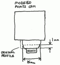
The timing disc is mounted underneath the points cam on the end of the commutator. The points cam has a small non-eccentric section between the eccentric section and the commutator. This section is turned to a taper of 20 degrees or so (not critical) such that it reaches a diameter of 15mm at a height of 1mm above the face that contacts the end of the commutator; from a little above that point (0.5-1mm, not critical) the taper ceases to be a taper and becomes parallel, as shown in this sketch:
The taper centres the 15mm hole in the timing disc on the axis of the points cam. The face of the points cam that contacts the commutator should then be experimentally turned or filed down so that when the centre bolt is tightened the timing disc is held sufficiently tightly that it can only be turned with difficulty by the fingers. An O-ring is then selected to sit between the disc and the body of the cam, on the parallel part of the turned-down section, such that it is slightly squashed when the cam is tightened down - only a little squashed, to avoid damaging the disc - this ensures that friction is maintained once the engine has warmed up. When using a steel timing disc, for additional friction a second O-ring may be placed between the disc and the end of the commutator. This will need to be sized to clear the raised end of the shaft in the middle of the commutator, ie. to sit on the paxolin rather than the metal, and be fairly thin. Don't use this variation with a plastic timing disc or it'll break when you tighten the centre bolt.
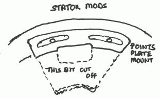
It is necessary to modify the stator of the generator in order to provide clearance for the timing disc. By removing the two screws for locking the timing adjustment, the sector plate on which the points are mounted can be removed, revealing a sort of pedestal thing with a big hole in it. The pedestal should then be cut off along an arc just inwards from the outside edge of the big hole, as in this sketch:
It is still possible to remount the points for backup purposes having done this. The force applied to the points follower by the cam is in a direction which tends to lift the sector plate up and away from the pedestal, so in normal operation it's not doing anything. The only force it has to resist is the thrust from a screwdriver applied to tighten or loosen the points clamp screw, so the only caveat is to be gentle when adjusting the points - an operation which is no longer necessary unless the electronics fail.
The points clamp screw has a few threads protruding beyond the back of the sector plate. These spare threads should be cut/filed off flush with the thread boss on the sector plate to prevent the screw catching on the timing disc.
Mounting the opto switch
The opto switch is soldered into the circuit board, which is then mounted on a bracket fixed to the boss on which the condenser is mounted in the standard setup (the condenser is still required and must be mounted somewhere else, it doesn't much matter where as long as its case is earthed). The bracket should be made/adjusted so that the timing disc is central in the slot of the opto switch and comes within 1-1.5mm of the bottom of the slot. The opto switch should be radially aligned with the disc. If the opto switch has mounting lugs it will be necessary to cut the bottom one off. The general arrangement is shown in this sketch:
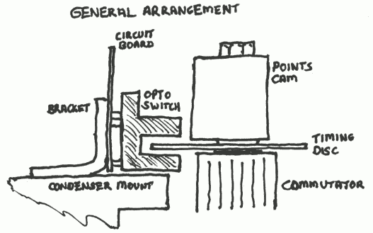
The bolts holding the circuit board to the bracket and the bracket to the condenser mount are not shown. It is unlikely to be possible to use the existing threaded hole in the condenser mount, and care must be taken when drilling a new one not to go right through and damage the field windings.
The electronics
The circuit diagram, and its relation to the original ignition system, is shown below. The layout is not critical and it is perfectly acceptable to knock it together on Veroboard.
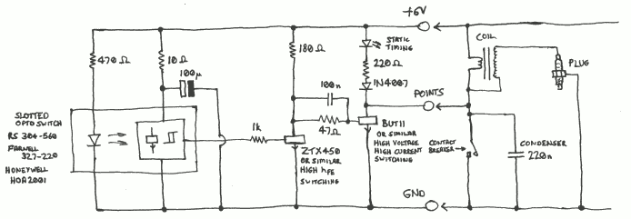
The opto switch should have a Schmitt trigger action and an output capable of sourcing current which is high when the beam is unobstructed. I used a Honeywell HOA2001 bought from RS as stock number 304-560. The Farnell stock number is 327-220. The HOA2001 has a single-ended output with integral pullup; one with a proper totem-pole output would be better, and may be necessary if a hard-to-drive transistor is substituted for the BUT11. (The HOA2001 was used simply because it was lying around spare from some other project.)
The ZTX450 transistor can be any high-hFE NPN switching type capable of handling a few hundred milliamps of collector current. A ZTX869 would be wonderful, and a BC337 will probably do.
The BUT11 transistor needs to be a high-voltage high-current NPN switching type capable of handling several amps of collector current and several hundred volts VCEO. Other suitable transistors can probably be scrounged from the primary stages of switched-mode power supplies such as old PC PSUs (though beware of MOSFETS) or from the line output stage of an old TV (beware of integral base-emitter resistors). The larger types may have heavy base-drive requirements and it may be necessary to use a ZTX869 in the ZTX450 position and/or use a totem-pole-output opto switch, then reduce the value of the 180 ohm resistor in stages until it works. The transistor should be mounted on a small heatsink.
The static timing LED goes out in the "points open" state. It can be omitted if desired, but it is useful, and all the best designs have an LED.
For use on a 12V system simply double all the resistor values except the 47 ohm one.
It is wise to test the circuit's operation on the bench using a spare coil, condenser, plug and battery, before fitting it to the bike.
The +6V connection needs to be fed from an ignition-controlled live, such as the +6V feed to the coil. The generator output terminal will not do. This does unfortunately mean running an extra wire in the loom down to the engine, but such is life.
The GND connection can be made in any convenient manner, such as through the mounting bracket.
The POINTS connection goes to the points (duh). The points can be retained for emergency use in case the electronics fail simply by adjusting the gap so wide that they never close. If the electronics fail all that needs to be done is to disconnect the POINTS connection and adjust the gap correctly.
This circuit can also be used as an "electronic relay" with standard points, to eliminate electrical (though not mechanical) wear on the points while avoiding pissing around with timing discs and opto sensors. Simply omit the opto sensor and its associated resistors and capacitor, replace the 1k resistor (from the base of the ZTX450 to the opto sensor) with a 220 ohm resistor to positive, and connect the points to the base of the ZTX450.
Setting the timing
The first thing to be done is to set the timing as normal on the points with the POINTS connection disconnected, then adjust the points gap so wide that they never close and connect the POINTS connection. This way, if the points are required in an emergency, all that is required is to set the gap correctly and the timing will be somewhere near right, if not bang on.
The piston should then be set at the appropriate height before TDC, the crank held still with a spanner on the centre bolt, and the timing disc rotated anticlockwise (as mentioned above, this should be possible but difficult) until the static timing LED goes out, then rotated further until it just comes on again. The timing is now set. It may be desirable to lock the timing disc with a couple of drops of glue once the timing has been set and checked to eliminate the possibility of things moving when the engine warms up, or for a more positive lock, drill a hole through the disc into the inner part of the commutator, tap the hole in the commutator, and insert a grub screw. The head of the screw must not protrude beyond the disc or it won't be possible to mount the points as a backup - it's acting as a pin, not a clamp. The inner part of the commutator is only paxolin - the copper bars are only on the outside - so it won't short anything when you put the screw in. Once the disc has been so locked, fine adjustment of the timing can be made by pivoting the pickup on its mounting bolt.