Copyright (C) 2004 Pigeon
This design is distributed under the terms of the Open Hardware General Public Licence, see file OHGPL.txt
General Description
This design replaces the incandescent bulbs in the stop, tail and indicator lights of an MZ or other motorcycle with a six-volt electrical system, with high-intensity "Lumiled" LEDs. This gives the following advantages:
- - A single Lumiled with a power consumption of around 1.2W gives a light output equivalent to a colour-filtered 21W incandescent bulb. The load on the electrical system is therefore considerably reduced. The power saved may be used to drive a more powerful headlamp bulb.
- - Unlike incandescent bulbs, LEDs do not burn out, and are not affected by vibration. Therefore, they do not need to be replaced. Accordingly, the light units may be permanently sealed and waterproofed with silicone sealant or similar, and connections to the LEDs made by soldered connections rather than contacts. The reliability of the lighting system is therefore much greater than the standard incandescent system.
- - The colour of the light is determined by the properties of the semiconductor material from which the LEDs are made, and not by filtering with a coloured lens. Therefore, should the lens be damaged or broken in an accident, the lights will continue to show the correct colour.
Driving the LEDs
Unlike an incandescent bulb, an LED requires external circuitry to limit the current taken to a safe value. This is generally done with a simple series resistor. However, this approach is not suitable for a six-volt automotive electrical system. The LED will drop about 3 volts in operation, and the supply voltage may vary from about 5 volts to 7 volts or more depending on the state of charge of the battery and the engine speed. This would result in a variation of about 2:1 in the voltage across the series resistor, with a consequent 2:1 variation in the brightness of the LED.
To avoid this problem the LEDs are driven from a simple constant current source:
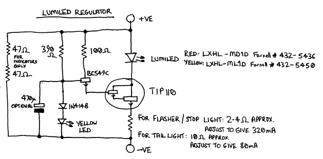
Points to note about this circuit are:
- - The current is nominally determined by the value of the emitter resistor of the TIP110. Due to component variations it will be necessary to adjust the value of this resistor to obtain the correct current, which is 320mA for an indicator or stop light and 80mA for the tail light. Approximately correct currents will be given by using 2.4 ohms for 320mA, and 10 ohms for 80mA. The actual currents should be measured and the resistor changed in accordance with the result. Use of a variable resistor is NOT recommended, for reasons of reliability. The 2.4 ohm resistors should be rated at 0.5W. Note that the absolute maximum permitted current for a Lumiled is 350mA.
- - Heat dissipated in the TIP110 has the unfortunate effect of causing the regulated current to rise. To avoid this the TIP110 should be heatsunk. This is most easily done by building the circuit in a diecast metal box and bolting the TIP110 to the box with suitable insulating washers and thermal transfer grease.
- - The purpose of the yellow LED is to provide the bias voltage for the constant current source. A green LED could be used instead, but a red or blue LED would NOT be suitable. There is no requirement for these bias LEDs to be visible.
- - The two series 47 ohm resistors across the entire circuit are to ensure correct operation of the flasher unit (see later). A single 100 ohm 0.5 watt resistor will do just as well. They are not required in the stop or tail lights.
- - The 470uF capacitor is optional and may be left out if desired. Its purpose is to cause the LED to turn on gradually, in a similar manner to an incandescent bulb, and thereby disguise the fact that an LED is fitted. This may be thought desirable in order to avoid possible problems due to incredibly stupid regulations which forbid the use of LEDs for vehicle lights unless incandescent bulbs are also fitted as the primary light source. (If anyone responsible for such regulations is reading this: GET A CLUE ALREADY.) If this capacitor is not fitted it may be possible to leave out the pair of 47 ohm resistors as well.
- - To waterproof the completed circuit and secure the components against vibration it should be potted. This is most easily done by using a hot air gun to melt plain white wax candles into the box until it is completely full of wax. In the unlikely event of a fault developing, it will then be possible to melt the wax out again to repair the fault. The box should be warmed slightly by directing the hot air gun on the outside before starting to melt the wax into it, to ensure that the liquid wax flows all around and underneath the circuit board. Do not direct the hot air gun onto the circuit board itself!
- - A separate regulator is required for each LED, making six for the complete system.
- - The regulator boxes can be mounted anywhere convenient. I mounted the regulators for the stop/tail lights and the rear indicators in one box attached to the rear lamp bracket, and the regulators for the front indicators in another box inside the headlamp shell.
- - Construction can be carried out using Veroboard and the layout is not critical.
Number Plate Light
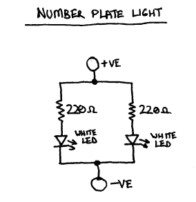
This is provided by a pair of ordinary (ie. non-Lumiled) high-intensity white LEDs. Since variations in brightness of the number plate light are not very important, current limiting is provided by series 220 ohm resistors. The circuit diagram (such as it is) is given below:
The Flasher Unit
It is not possible to use the standard thermal flasher unit as the LED lights do not draw sufficient current to operate it. An electronic flasher unit is used instead:
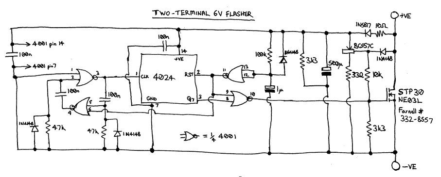
Points to note about this circuit are:
- - It is polarity-sensitive. Unlike a thermal flasher, it must be connected the "right way round". It is not therefore compatible with the somewhat awkward arrangement in the MZ where the same indicator bulb functions both as an indicator warning lamp and a charge warning lamp. The connection from this bulb should be removed from flasher terminal 49a and connected to terminal 15 of the ignition switch. A separate indicator warning lamp may be added according to the arrangement below:
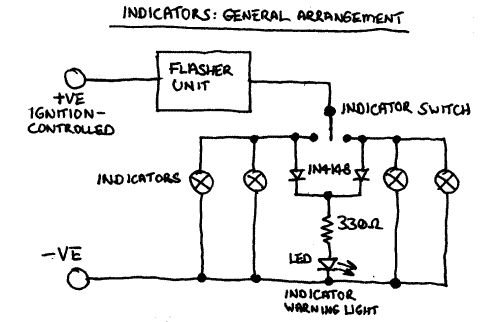
Personally, I'm not too keen on the standard "dual-function" warning lamp arrangement anyway, and prefer the revised arrangement. A second alternative would be to construct and mount the regulators for the front indicators in such a way that the yellow bias LEDs are visible.
- - It is a two-terminal unit, so in the "on" state it shorts its terminals and draws power from an internal reservoir capacitor.
- - It is designed to have a "rapid start-up". Conventional flashers commence operation in the "off" state, so there is a significant delay between operating the indicator switch and the indicators producing light. This unit comes "on" as soon as it has charged up its internal reservoir capacitor, so when the indicator switch is operated the indicators produce an indication almost straight away. The function of the logic around the "reset" and "Q7" pins of the 4024 divider is to allow time for the reservoir capacitor to charge before the unit goes into the "on" state.
- - For this logic to operate correctly, it is necessary for power to be applied to the unit with a reasonably fast edge. This is why, if the indicator regulators are built with the "slow-start" capacitors, the two 47 ohm bypass resistors are also required.
- - The function of the BC557C and associated resistors and diodes is to rapidly discharge the reservoir capacitor when power is removed, to prevent the unit getting stuck in an indeterminate state if power is reapplied before the reservoir capacitor has fully discharged.
- - The specified STP30NE03L MOSFET is a "logic-level" type, ie. with a low gate threshold voltage. Other types may be used but they must be "logic-level" types. The type specified is capable of driving incandescent bulbs as well as LEDs. No heatsinking is required in either case.
Note concerning this MOSFET: If the particular MOSFET specified is hard to find, don't worry. MOSFET types come and go like leaves on a tree and it is common to specify one and then find a few months later that it has mysteriously disappeared from the catalogues... Just pick another one with logic-level gate drive and Rds(on) as low as possible.
- - As with the regulator units, it is recommended that the flasher unit be potted in wax for waterproofing and vibration-proofing.
- - Construction can be carried out using Veroboard and the layout is not critical.
Mounting the Lumileds
Lumileds require a certain degree of heatsinking, unlike normal LEDs. They are supplied mounted on small hexagonal aluminium plates which should be bolted to some form of heatsink with thermal transfer grease. The brass or copper strips referred to below will provide adequate heatsinking. Connection is made by soldering to pads on the upper surface of the plate. The plate is electrically isolated from the LED, so no insulating washers are required, but care should be taken that the heads of the mounting bolts do not touch or overlap the connection pads.
Indicators
A cross-section of the modified indicator housing is shown here:
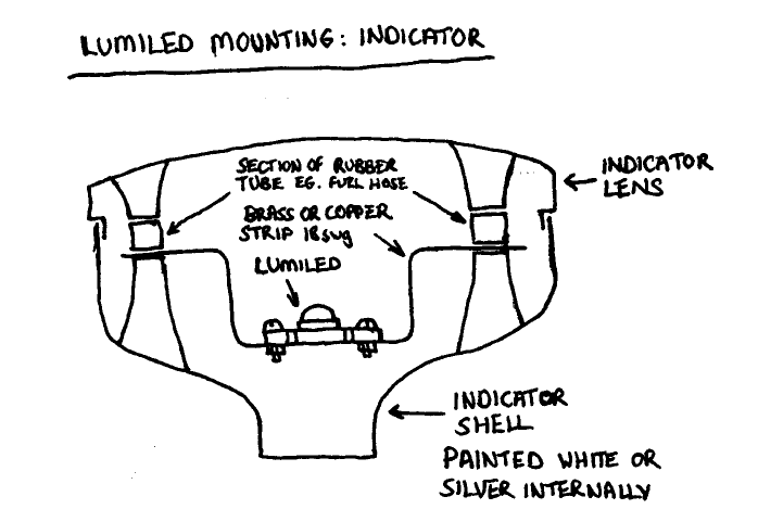
The existing bulbholder metalwork is completely removed and the interior of the shell is painted white or silver to maximise light output. A strip of brass or copper, thickness 18swg or so, is bent into a U-shape and suspended between the bosses for the lens fixing screws. Holes are drilled in the strip for the lens fixing screws to pass through. Two small lengths of rubber tube, such as fuel hose, are cut to fill the gap between the metal strip and the bosses on the lens, such that when the lens is screwed on the pieces of tube are slightly compressed and hold the metal strip firmly in place. The Lumiled is bolted to the middle of the strip with some thermal transfer grease. Silicone sealant is used around the rim of the lens, in the cable entry hole, and in the holes for the lens fixing screws, to produce a completely sealed indicator unit.
Stop / Tail Light
A cross-section of the modified stop/tail light housing is shown here:
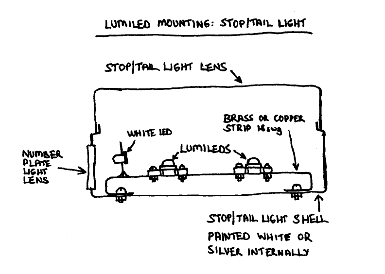
The existing bulbholder metalwork is completely removed and the interior of the shell is painted white or silver to maximise light output. A strip of brass or copper, thickness 18swg or so, is bent into the shape shown and bolted inside the shell; the Lumileds are then bolted to the strip, using thermal transfer grease, and centred behind the centres of the lens patterns provided for the original bulbs. A smaller piece of strip is soldered perpendicularly to the main carrier opposite the lens for the number plate light, to screen the red light off from the number plate light. The white LEDs for the number plate light are glued into holes drilled in this screen. Silicone sealant is used around the rim of the lens, in the cable entry hole, and around the lens fixing screws, to produce a completely sealed unit.
Lumileds
Note: The above LEDs have been discontinued by Luxeon. The manufacturer's recommended replacements are:
Stop and tail: SR-01-D0040
Indicators: SR-01-L0040
They may be ordered direct from the manufacturer using the above links.
Downloads
The design is available for download in two formats: for proper operating systems and for Microshite. (WinZip claims to be able to handle .tar.gz format but people never seem to be able to make it work.)