Volvo 164 electric fan thermostat
While this circuit could be fitted to any vehicle, it was designed for
use on my Volvo 164. The original mechanically-driven viscous coupling
fan had a loose centre bearing and made alarming clanking noises at
certain revs, so rather than try and arse about finding a replacement
I figured I'd fit an electric fan and possibly save an mpg or two at
the same time.
Of course, being a pigeon, I couldn't use a conventional temperature
sensor in the radiator. For one thing, I'd have had to drill a hole in
the rad to fit it. I don't really want to do that. Also, they're shit.
I've lost count of the number of cars I've had to bodge by shorting
the defunct temperature sensor so the driver can get home (most of
them carry on driving like that indefinitely...) not to mention the
number of shagged head gaskets from the same cause.
A favourite temperature sensing method of mine is to use the variation
in voltage drop across a diode being driven from a constant current
source. So this is what I did. Four 1N4007s in series on a scrap of
veroboard are held to the radiator with a brass clip - the Volvo 164
has a proper radiator, made of copper and brass, so it is easy to
solder a brass clip to it. In addition to the clip, the diodes are
glued to the radiator with Araldite. This is more for reasons of
thermal contact than mechanical fixing, because the Araldite goes all
gooey and soft at operating temperature, so the clip does the work of
holding the diodes in place.
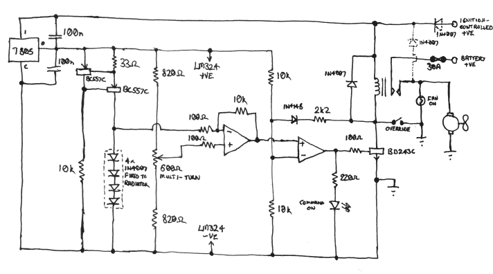
The above circuit diagram shows the rest of the gubbins. An op-amp
circuit detects the fall in voltage across the string of diodes with
rising temperature and operates a relay to switch the fan on. A
multi-turn pot sets the switch-on temperature; I set mine to 92 deg C.
A small amount of hysteresis is provided to ensure clean switching.
The relay needs to be a beefy item to handle the switch-on surge of
the fan, which is considerable. I used a glow plug timer relay off a
diesel Peugeot. This also provided a handy housing to mount the
circuit board in, fitting it in place of the original timer circuit
board.
The two diodes shown dotted are required if you want to duplicate the
function of modern electric fans in continuing to run when the
ignition is switched off. I don't regard this as a very useful
function unless you also have an electric water pump still running, so
my unit does not include them.
The "command on" LED is for bench testing the unit without a fan
connected. It may not be strictly necessary but all the best designs
feature an LED. The "override" switch and "fan on" indicator light are
dashboard fittings - the light to indicate that the fan is receiving
power (I couldn't be arsed to go all the way and fit a rotation
sensor) and the switch to bring it on manually if you don't like the
look of the temperature gauge. The light provides the auxiliary
function of "motorway speed limit indicator" - when I get up to about
70mph the fan starts windmilling and generates enough juice to make
the bulb glow.
I am pretty sure the circuit diagram is correct - I have checked it
over several times - but I cannot be totally certain as it is drawn
from memory, and I can't be arsed to take the unit out of the car and
dismantle it and trace it out. The reason for this vagueness is that
the original circuit diagram
tunnelled
out of the folder of Volvo-related documents in which it was being
kept. If by any chance someone reading this article has discovered the
mysterious appearance of a very similar circuit diagram drawn in
pencil on a bit of greasy lined A4, please
contact me.
Back to Pigeon's Nest
Be kind to pigeons
![]()