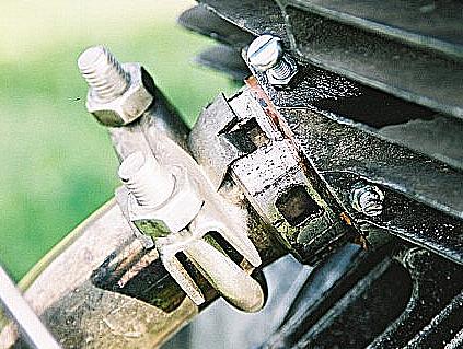
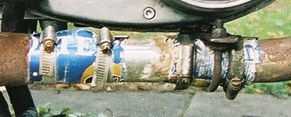
The exhaust retaining device
It has to be said that this bike isn't particularly ratty. I don't deliberately rat things (bikes or otherwise), I just let them evolve into a state of rattiness as things go wrong and I fix them by some unconventional means. This is probably the best example on the bike at the time of taking the photos. The thread in the cylinder boss that the exhaust collar screws into is buggered, and the thread on the collar itself isn't too clever either. Copper shim in the threads takes up the slack, and the exhaust clamp secures the little locking device thingy to stop the thing vibrating round and unscrewing itself. This worked until the threads got more buggered and wouldn't hold even with two thicknesses of copper shim, so I drilled and tapped two holes for the two bolts with locknuts on, which go right through the boss and the collar and hold everything in place. Well they did until one of the bolts, locknut notwithstanding, fell out. I made a temporary repair by stuffing a woodscrew I found at the side of the road into the hole, but it wasn't the same. It's had the cylinder and the retaining collar replaced now with ones that do have a decent thread, so the little bolts and the copper shim are gone, but the locking device thing and the exhaust clamp are still there, just in case.
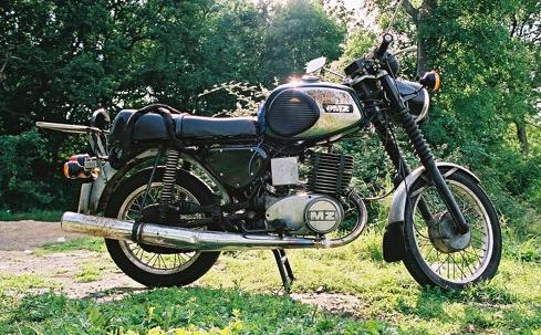
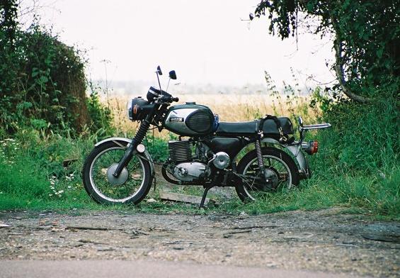
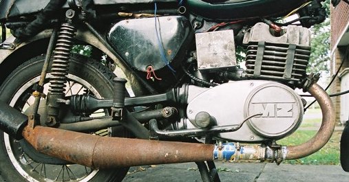
The bike from the right hand side.
That exhaust is no longer on it. It now has a Tuningauspuff (I think that's a brilliant word) from TKM Racing which, to get the pipe length right, is connected to the downpipe by a third length of straight pipe, the joints being sealed and retained by strips of beer can ally lined with exhaust paste and clamped with jubilee clips. Much more respectable... but not the final development. The exhaust in the photo is not a TS exhaust but an ETZ one, which has too long a front cone; the Tuningauspuff has too short a front cone. I am intending to fit a genuine TS exhaust, which has a front cone length intermediate between the two, and should suit the bike better than either.
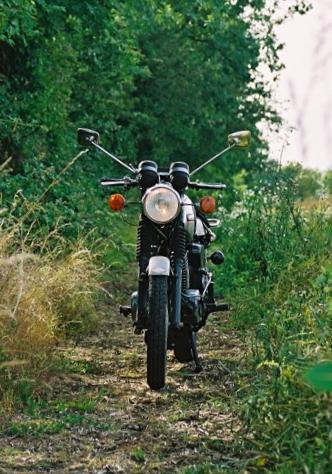
Front view.
Looks fairly standard from this angle apart from the mirrors. I like long mirror arms so I can see something more useful than my elbows. Not revealed by the photo are the 6V halogen headlamp bulb from Goffy and the 6V LED indicators of my own design. Well, the pilot light is on, but you can't see it's a halogen. And the indicators are flashing, but I didn't manage to press the shutter at the right moment, so you can't see that either.
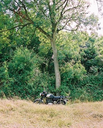
Neil's Heavy Motorbike Encounter
Hey wow, I was walking through this field, right, and like right under this tree, right, there was like this motorbike! With like an engine in it, and black oily bits. Heavy!
The bike from the left hand side.
It's hard to see any of its distinctive features from this angle. This is probably because the design of the bike puts most of the interesting stuff on the other side. It now has an SU HS2 carb on it, not that you can really see the original carb in this photo anyway.
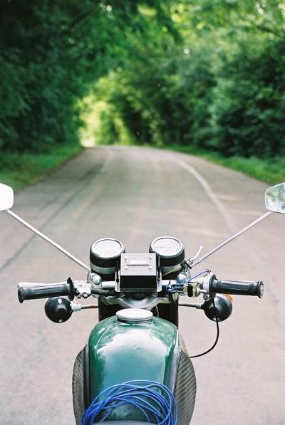
Looking down the road over the handlebars.
The box in the middle is a digital voltmeter, which enables me to check that my design for an electronic voltage regulator, replacing the original mechanical thing, is behaving itself. Which, so far, it seems to do. There is a spatial conflict between the original mounting position for the choke lever and the mirror clamps, so the choke lever is fixed to the mirror arm with cable ties. (The Dellorto carb has a lever on the carb for the choke and doesn't use the cable control, but I don't see that as a reason to take the cable control off...) The indicator switch was missing when I got the bike, so now there is a waterproof toggle switch mounted on a strip brass bracket. Not quite visible is the microswitch to activate the brake light from the front brake lever, a feature unfortunately lacking from the original bike. You can see the wire going to it though. The coil of blue wire is the ground electrode for the stray capacitance sensor. When parked this is laid on the ground, and if it or the bike is touched it lets me know. There's this really cool stuff called Marine Epoxy. One day the bike didn't want to start, so I bumped it, tripped over my own feet trying to get on board and wobbled gently into a wall at about 3mph. This broke the left hand indicator. Marine Epoxy un-broke it.
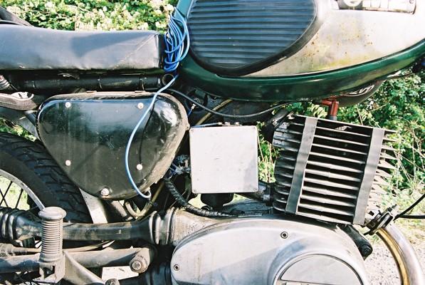
Non-standard bits of the electrical system.
The grey box contains the electronic voltage regulator and the electronic flasher unit for the LED lights. It is attached to the mounting bracket for the coil, which now lives inside the battery compartment. This keeps it out of harm's way, and allows me to route the HT lead in such a way that if the insulation leaks on a wet day it doesn't electrocute my right leg. Below the grey box there can be seen a length of spiral wrap, which encloses the cable to the alternator. The whole bike is wired in 2.5 sq mm tri-rated. No pesky 6V voltage drop problems here.
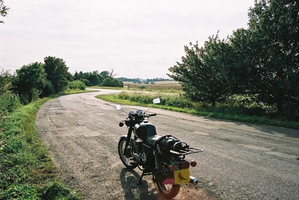
The bike from the rear.
Not much to say about this view. It's the back end of a bike. The lights have LEDs in, but again you can't actually see that in the photo. If it was running, there would be blue smoke coming out of the exhaust, but it isn't, so there isn't. I suppose it would have been fun to lock the front brake on, start it, put it in gear and chuck some dust under the back wheel, then take the photo from a bit further back, so the dust cloud makes it look like it's tanking down the road without a rider. Maybe I'll try that one day.
The SU carburettor.
The original BVF carb has been replaced with an SU HS2, which gives better fuel economy, better idling and bottom end flexibility, easier mixture adjustment for cold/hot weather (no changing jets in freezing conditions) and a little bit more on the top end. Currently it is fitted with a GY needle though this is subject to further experimentation.
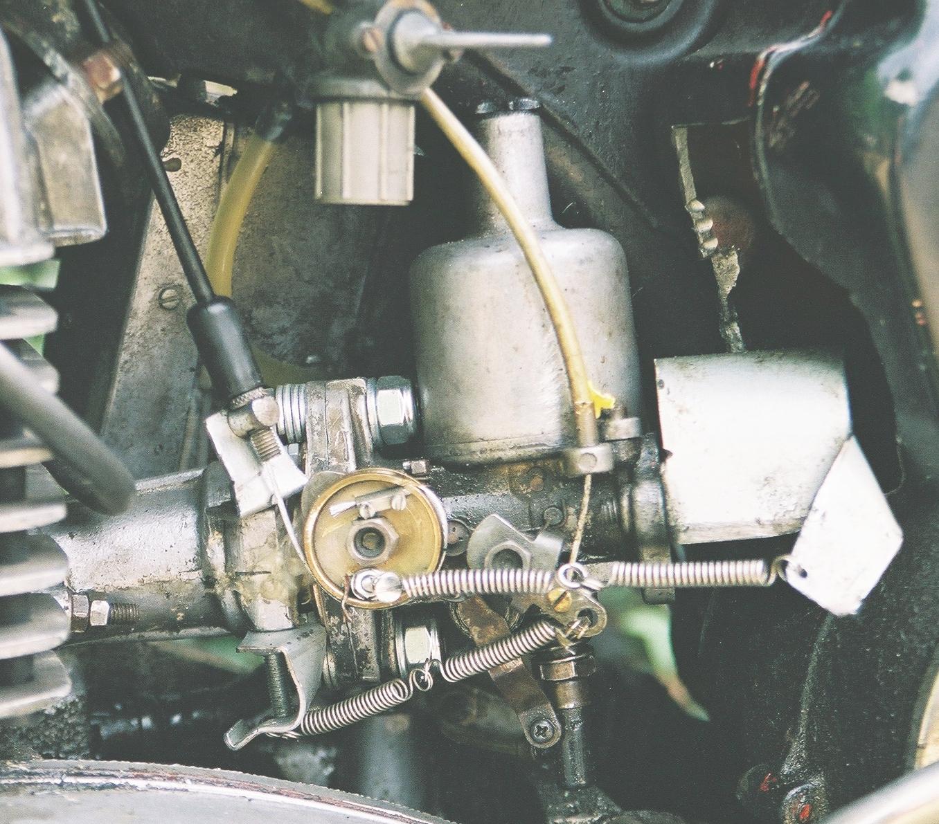
Here we see the mounting arrangements (click on the pic for a high-res version). The carb flange is bolted to the flange of a 1.25" plughole as used with a bathroom sink. The pipe bit of the plughole is cut off at the level of the slots where the overflow goes in, and fits in the end of the original intake stub pretty well with a couple of beer-can shims; unfortunately you can't see it very well as most of it is inside things. The inside of the plughole is lined with epoxy filler which has been sanded so as to produce a smooth inner surface to the pipe without any abrupt changes in diameter.
The plug that went in the plughole was of the type that seals with an O-ring; the O-ring sits in a groove which makes the plug the ideal thing for connecting the throttle cable to the butterfly spindle. This bit is clearly visible. The outer of the throttle cable sits in a bicycle brake adjuster thing on a bracket attached to the inlet stub. One return spring is visible attached to the plug; not visible is the clock spring round the butterfly spindle, which is hidden behind the plug. This combination of springs provides an approximation to a constant return force on the throttle cable, and gives a better throttle feel than the original, while still having plenty of force to pull against the friction of the throttle cable and ensure the throttle closes.
The choke cable arrangements are also clearly visible. The choke cable sits in the termination provided on the carb body and attaches to the choke mechanism with a screw-on nipple, the head of which is visible. A return spring leads to a bracket attached to the inlet stub.
The metal thing attached to the mouth of the carb is a strip of steel shaped like a Nissen hut. Its function is to keep rain from getting in the mouth of the carb when the bike is parked up, and it also provides a handy attachment point for the throttle return spring. Since the photo was taken, a 30mm intake trumpet has been added underneath the Nissen hut, not so much for airflow reasons as to assist in keeping the rain out - any rain that goes through the gap visible between the Nissen hut and the suction chamber, instead of trickling into the mouth of the carb, runs round the outside of the trumpet and drips off the bottom.
The big hole in the side of the airbox is a legacy of my experiments with different intake arrangements. I tried the carb with no intake plumbing (as shown), with the air filter adaptor from its car application attached (but no filter), and with the air filter adaptor used as an adaptor to attach the long rubber snorkel thing that was part of the original MZ setup. Since the air filter adaptor sticks up at a funny angle, I had to cut a big hole in the airbox to make room for it. It is somewhat unfortunate that the result of my experiments was that it performs best with no intake plumbing at all, as I now have a big hole in the airbox which I can't think of a use for.
The float chamber is not visible as it is on the other side of the carb. SUs are available in mirror image forms - one with the float chamber on the right and the throttle and choke gubbins on the left (as mine), and one the other way round. Using one which is the other way round would be a complete arse; the throttle cable stuff would be more awkward to get to, and the float chamber would probably catch on the side cover. The SU part number for the model and variant of carb I have used is AUD344R (the R denotes float chamber on the right).
A couple of unrelated items are just visible in this pic, which is of later date than the preceding ones - if you check the fins it is apparent that the TS head has been replaced by the vertical-finned ES type with the spark plug in the right hand side. I have fitted this head with an additional spark plug in the diametrically opposite position, on the left hand side, to produce a twin-spark setup. This is driven using a Sparkrite aftermarket CDI unit for a car, modified to run off 6V and achieve greater efficiency, feeding a Ford coil. See below...
The twin-spark head
From the right hand side, it looks just like an ordinary ES head. But the spark plug lead heads off in a strange direction, to end up at the Ford coil, which can just be seen nestling behind the horn (it is held in place by a big muckle cable tie that goes round the frame tube under the tank). The CDI unit is hidden inside the battery compartment.
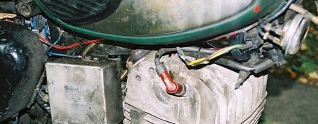
From the left hand side, the differences are more apparent. The coil can be clearly seen, and nobody could miss the spark plug.
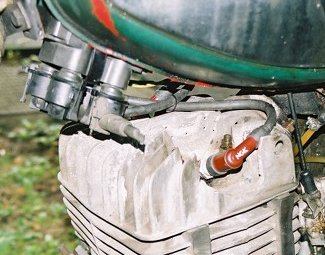
I cut the fins away with an angle grinder - an awkward job, which deposited a significant amount of aluminium powder in my carpet; have to make sure I don't grind rust into the carpet in the same place, or I could end up with a Hindenburg - then drilled and tapped a hole for an extra plug. The thread is M14x1.25. The metal is thicker on this side of the head, so an ES rather than HS plug (NGK marking system) is necessary to get the required reach. I get funny looks when I go into a bike shop and ask for one BP7HS and one BP7ES - they think I don't know what I'm doing and get all wary because they think I'm going to be bringing the plugs back and asking for different ones. So I explain the conversion in tedious technical detail until their eyes glaze over :-)
A couple of days after doing this conversion I had a bit skimmed off the top of the barrel so that I could drop the squish clearance to 1.0mm. That, the twin-spark conversion and the SU carb conversion all had roughly the same effect - making the engine run better, with more torque and less misfiring, at low revs and low throttle settings, the area where two-strokes have the greatest difficulty in igniting the mixture due to scavenging deficiencies. The effects of the three mods are pretty much additive. The result is a bike that is easier to ride around town and uses less fuel - I reckon I get about 65mpg on 97 octane (it doesn't like plain 95 with the raised compression). These aspects make the conversions worthwhile; I wouldn't recommend them purely to make the bike go faster.
The more rapid flame spread given by the twin spark system means it runs best with a bit less advance than standard. I run it a tad retarded from 2.5mmBTDC.
The protruding-nose plug variant - BPxxx as opposed to the standard Bxxx - is a worthwhile mod on a standard bike. The protruding nose (which is what the P means) gives better flame initiation than the standard plugs. There are no clearance worries.
The "Tuningauspuff"
This shows the mounting of the Tuningauspuff, with the extra length of pipe between it and the header. The front cone on this exhaust, at 300mm or so, is too short for a road engine and compromises the power band. Without the extension pipe, it's trying to make power at over 6000rpm, which is at odds with what the rest of the engine is happy with. With the extension, it's much better in the midrange, but runs out of puff a bit at the top end. However, that is the better compromise for normal road use. A further benefit is that it makes the bracket on the exhaust align with the stay; without the extension, the stay has to be bolted to the end of the silencer can.
Here is a close-up of the extension tube, and its beer can and exhaust paste leak-proofing arrangements. The steady bracket is also non-standard, because that was missing when I got the bike, so I made something up out of odds and ends.
Back to pictures index
MZ Page
Be kind to pigeons